Apparatus for treating atherosclerosis

a technology for atherosclerosis and apparatus, applied in the field of apparatus for treating atherosclerosis, can solve the problems of difficult and time-consuming procedures, difficult insertion of guidewires into branch vessels, and often difficult occlusion treatment, so as to prevent atherosclerosis and minimize the axial length of gaps

Active Publication Date: 2006-02-02
THE CLEVELAND CLINIC FOUND
View PDF25 Cites 21 Cited by
  • Summary
  • Abstract
  • Description
  • Claims
  • Application Information

AI Technical Summary

Benefits of technology

[0010] The present invention relates to an apparatus for interventional treatment of atherosclerosis at a vascular bifurcation formed by a junction of a branch vessel and a main vessel. The apparatus comprises structure for receiving a first guidewire positioned in the main vessel and a second guidewire positioned in the branch vessel. An exit for the second guidewire is located in a central section of the structure. A first balloon portion is secured to the structure so a proximal end is located adjacent the exit. A second balloon portion is secured to the structure so a distal end is located adjacent the exit on a side opposite the first balloon portion. An annular gap is defined between the proximal end of the first balloon portion and the distal end of the second balloon portion. The annular gap, at a radial outermost location relative to the structure, has a width that is equal to or less than a width of the annular gap at a radially innermost location relative to the structure. The second guidewire is extendable through the annular gap. The apparatus also comprises an expandable stent that is mountable about the first and second balloon portions and is expandable by the first and second balloon portions into engagement with the main vessel at the vascular bifurcation.
[0011] According to another aspect, the present invention relates to an apparatus for interventional treatment of atherosclerosis at a vascular bifurcation formed by a junction of a branch vessel and a main vessel. The apparatus comprises structure for receiving a first guidewire positioned in the main vessel and a second guidewire positioned in the branch vessel. An exit for the second guidewire is located in a central section of the structure. A first balloon portion is secured to the structure so a proximal end is located adjacent the exit. The proximal end of the first balloon portion has an arcuate end surface. A second balloon portion is secured to the structure so a distal end is located adjacent the exit on a side opposite the first balloon portion. The distal end of the second balloon portion also has an arcuate end surface. The arcuate end surfaces of the first and second balloon portions extend toward one another and define an annular gap therebetween through which the second guidewire is extendable. The apparatus also comprises an expandable stent that is mountable about the first and second balloon portions and is expan

Problems solved by technology

Difficulties often arise when treating an occlusion that occurs at or near a vascular bifurcation formed by an intersection of a main vessel with a branch vessel.
This procedure is often difficult and time consuming.
One common difficulty that is encountered during this procedure involves threading a guidewire for the balloon catheter used to deliver the second stent through the struts of the implanted first stent.
Another common difficulty arises

Method used


Image

  • Apparatus for treating atherosclerosis
  • Apparatus for treating atherosclerosis
  • Apparatus for treating atherosclerosis

Examples


Embodiment Construction

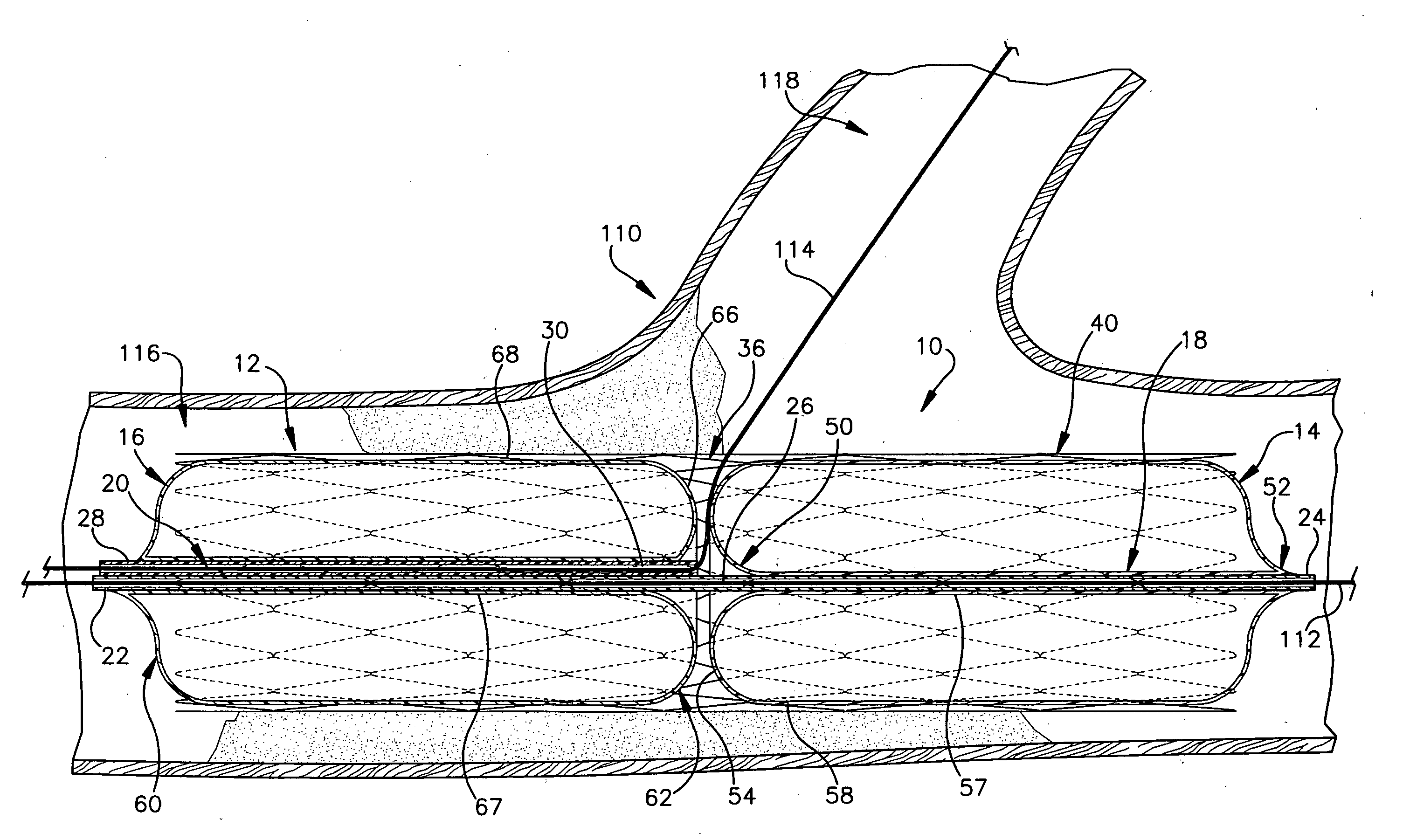
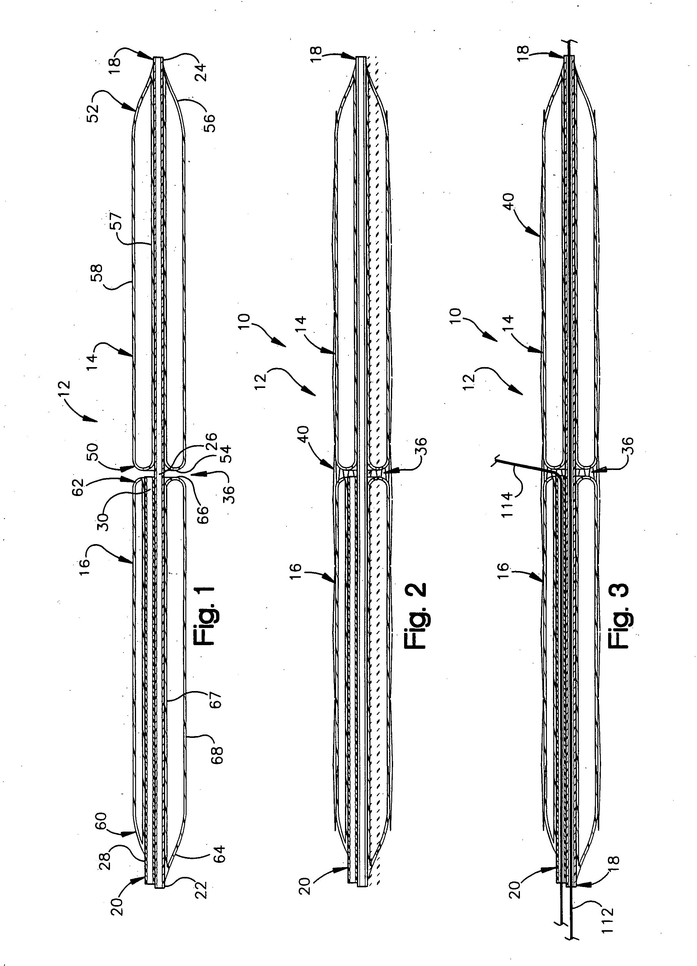
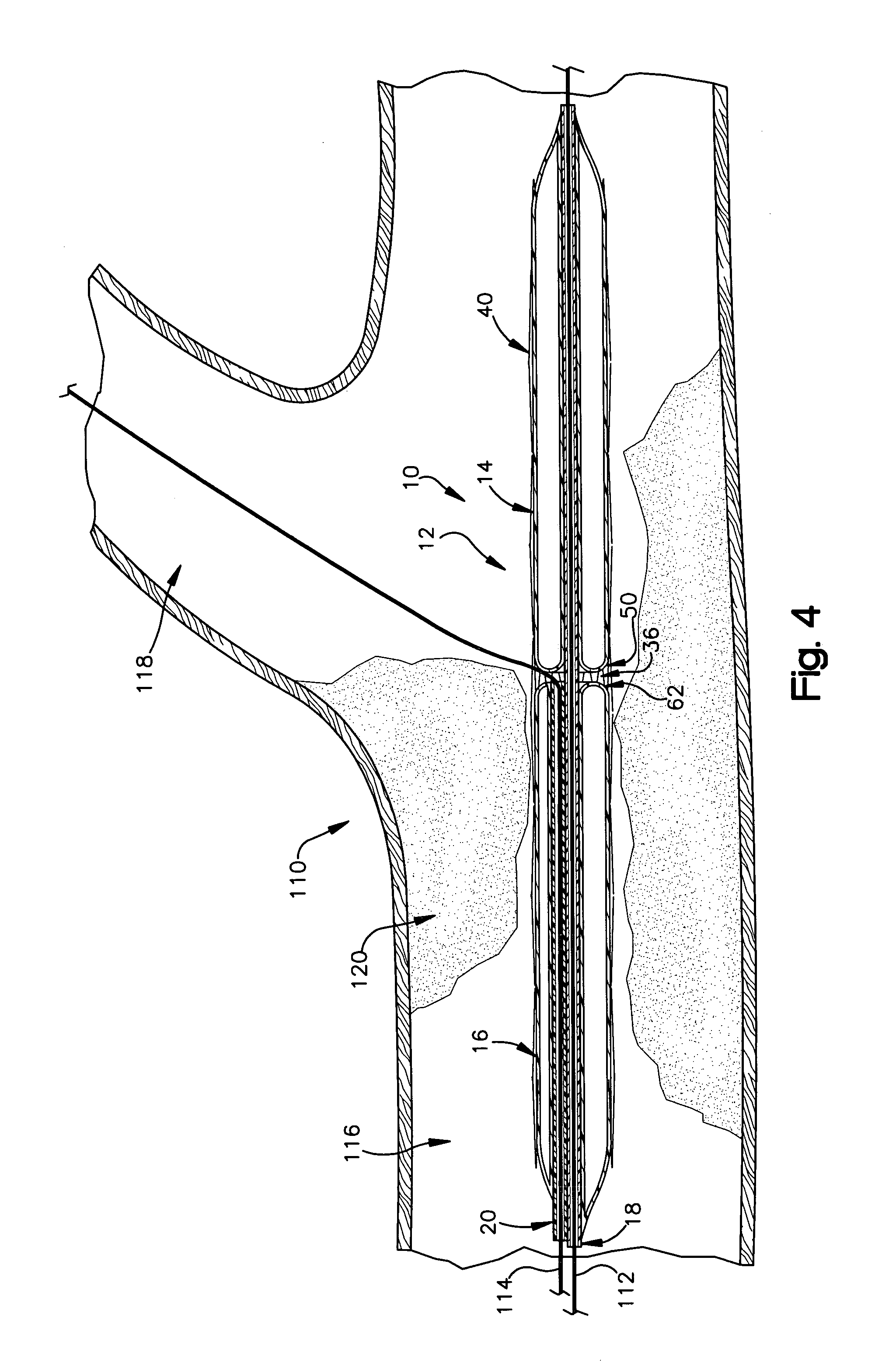
[0022] The present invention relates to an apparatus 10 (FIG. 2) for treating atherosclerosis, and is particularly directed to an apparatus 10 for interventional treatment of atherosclerosis at a vascular bifurcation formed by a junction of a branch vessel with a main vessel. As described more fully below, the apparatus 10 includes a balloon catheter 12 that is particularly useful in delivering and deploying a stent at or adjacent a bifurcation in a blood vessel. The apparatus 10 of the invention may be used with any conventional balloon catheter delivery system, including an over-the-wire balloon system or a rapid exchange balloon system. In addition, the apparatus 10 may be used to deploy any conventional balloon-deployable stent. Therefore, the scope of the present invention should not be limited to the exemplary delivery system and stents discussed below.

[0023]FIG. 1 illustrates the balloon catheter 12 of the apparatus 10. The balloon catheter 12 has first and second balloon po...


PUM


Abstract

An apparatus for interventional treatment of atherosclerosis at a vascular bifurcation includes structure for receiving a first guidewire and a second guidewire. An exit for the second guidewire is located in a central section of the structure. A first balloon portion is secured to the structure so a proximal end is located adjacent the exit. A second balloon portion is secured to the structure so a distal end is located adjacent the exit. An annular gap is defined between the proximal end of the first balloon portion and the distal end of the second balloon portion. The annular gap, at a radial outermost location relative to the structure, has a width that is equal to or less than a width of the annular gap at a radially innermost location relative to the structure. The apparatus also comprises an expandable stent that is mountable about the first and second balloon portions.

Description

RELATED APPLICATION [0001] This application is related to U.S. Provisional Patent Application Ser. No. 60 / 591,385, filed Jul. 27, 2004, the subject matter of which is incorporated herein by reference.TECHNICAL FIELD [0002] The present invention relates to an apparatus for treating atherosclerosis, and is particularly directed to an apparatus for interventional treatment of atherosclerosis at a vascular bifurcation formed by a junction of a branch vessel with a main vessel. BACKGROUND OF THE INVENTION [0003] Balloon catheters are commonly used to treat certain conditions of a blood vessel, such as a partial or total occlusion or lesion of the vessel that may be caused by, for example, atherosclerotic plaque or thrombosis. In an angioplasty procedure, a guidewire is inserted into an occluded blood vessel. A balloon portion of a catheter is advanced over the guidewire to the site of the occlusion. When the balloon portion is properly positioned relative to the occlusion, the balloon po...

Claims


Application Information

Patent Timeline
IPC IPC(8): A61F2/06
CPCA61F2/856A61M25/1011A61F2/958A61F2/954
Inventor GURM, HITINDERYADAV, JAYCHEN, JI-FENG
Owner THE CLEVELAND CLINIC FOUND
Why Eureka
Try Eureka