[0018] A number of alternative embodiments of the illumination and imaging
optics are possible in which multiple optical and structural functions can be combined into a smaller number of parts in order to lower the
assembly cost and simplify the structure. For example, some of the illumination
optics and imaging optics can be incorporated into one or more features in or on the dome, multiple optical elements can be molded into a single piece, and mechanical positioning and attachment features can be incorporated into the optical elements and / or the housing in order to hold the components in position and alignment. Refractive, reflective, or diffractive optics and different
light source geometries can be used.
[0019] In alternative embodiments, the housing can be configured to lie in a substantially perpendicular or substantially parallel orientation with respect to a plane of the panel, and the dome can have additional features or textures to provide visual and tactile indication of the position and orientation of the sensitive area. Instead of, or in addition to,
grazing incident illumination, the sensitive area can be illuminated more normal to its surface by a different configuration of light source and illumination optics. The dome can be textured to give it diffusing properties, which will make the device relatively insensitive to the motion of objects that are not close to, or in contact with, the surface of the dome closest to the user. Additional light sources or decorative textured or
colored features can be provided to enhance the aesthetics and ergonomics of the device. Switches or other controls can be integrally combined with the housing and / or dome of the basic cursor positioning device to provide selection or other additional functions in addition to cursor pointing.
[0021] In this cursor control device, the interior of the inner housing can be fluidly sealed from an exterior of the inner housing. This provides an additional degree of protection for components disposed within the inner housing. The outer shell can be removable from the cursor control device, and since the inner housing is sealed the outer shell can be removed and / or replaced without exposing the components disposed within the inner housing to the environment the inner housing remains fluidly sealed when the outer shell is removed.
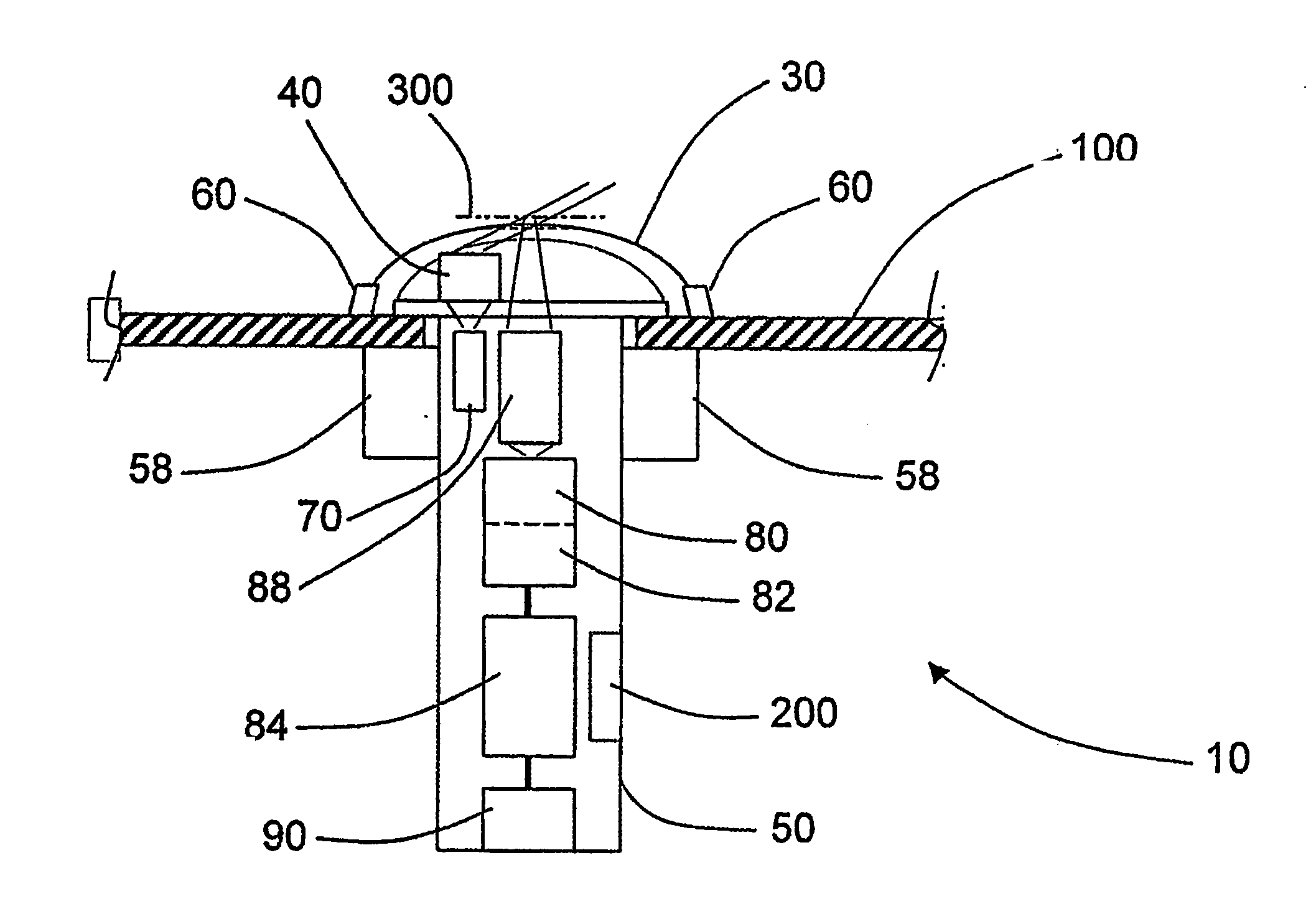
[0023] According to another aspect of the present invention, an optical engine for a cursor control device is provided that includes a housing, an
imaging lens element integrally formed into the housing, a light source disposed within the housing for emitting light along an illumination
optical axis, and a sensor disposed within the housing for sensing light along an imaging
optical axis that intersects the
imaging lens element. The optical engine can further include an illumination lens element integrally formed into the housing, wherein the illumination
optical axis intersects the illumination lens element. The light source can be a
light emitting diode, for example that emits
infrared light. The
imaging lens element can be such that it focuses light from a focal plane onto the sensor, wherein an angle between the illumination optical axis and the focal plane is in a range from 0 degrees to 45 degrees, more preferably from 15 degrees to 35 degrees, and most preferably 30 degrees. The optical engine can further include a
filter element disposed along the imaging optical axis for selectively transmitting light to the sensor. The
filter element can be disposed between the imaging lens and the sensor. The
filter element can be such that it transmits
infrared light and prevents transmission of visible light.
[0048] According to another aspect of the invention, a cursor control device is provided that comprises a first sensor, a light source, and a controller that includes means for receiving intensity information indicative of an intensity of sensed light, and an adaptive illumination control means for controlling the intensity of light emitted by the light source based on the intensity information. The adaptive illumination control means can control the intensity of light in order to optimize the
dynamic range of the first sensor. The adaptive illumination control means can control the intensity of light based on a
shutter value
signal received from the first sensor. The adaptive illumination control means can control the intensity of light based on a contrast
signal received from the first sensor. The intensity information can be received from the first sensor, or it can be received from a second sensor in which case the adaptive illumination control means can control the intensity of light in order to optimize the
dynamic range of the first sensor.

