Mixed tuned hybrid blade related method

a hybrid blade and hybrid technology, applied in the field of hybrid composite blades, can solve the problem of unsatisfactory natural frequency tuning, and achieve the effect of reducing or more effectively damping vibrations

Inactive Publication Date: 2006-02-09
GENERAL ELECTRIC CO
View PDF16 Cites 22 Cited by
  • Summary
  • Abstract
  • Description
  • Claims
  • Application Information

AI Technical Summary

Benefits of technology

[0006] This invention relates to the expansion of hybrid blade technology for the

Problems solved by technology

Thus, an undesirable natural frequency may be “tuned out” through the selection

Method used


Image

  • Mixed tuned hybrid blade related method
  • Mixed tuned hybrid blade related method
  • Mixed tuned hybrid blade related method

Examples


Embodiment Construction

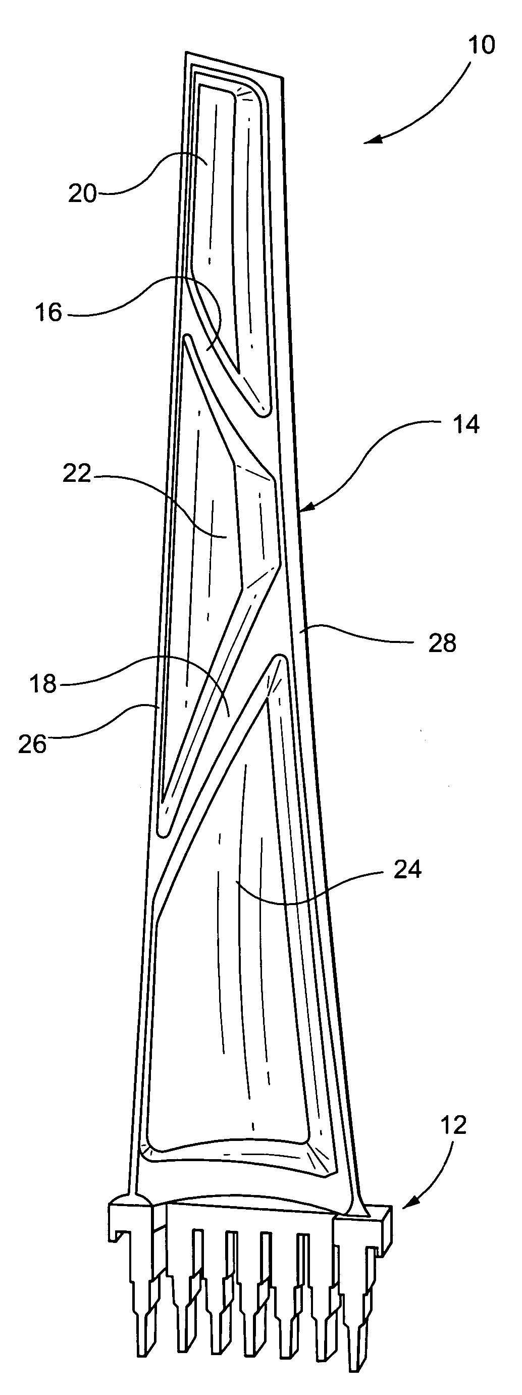
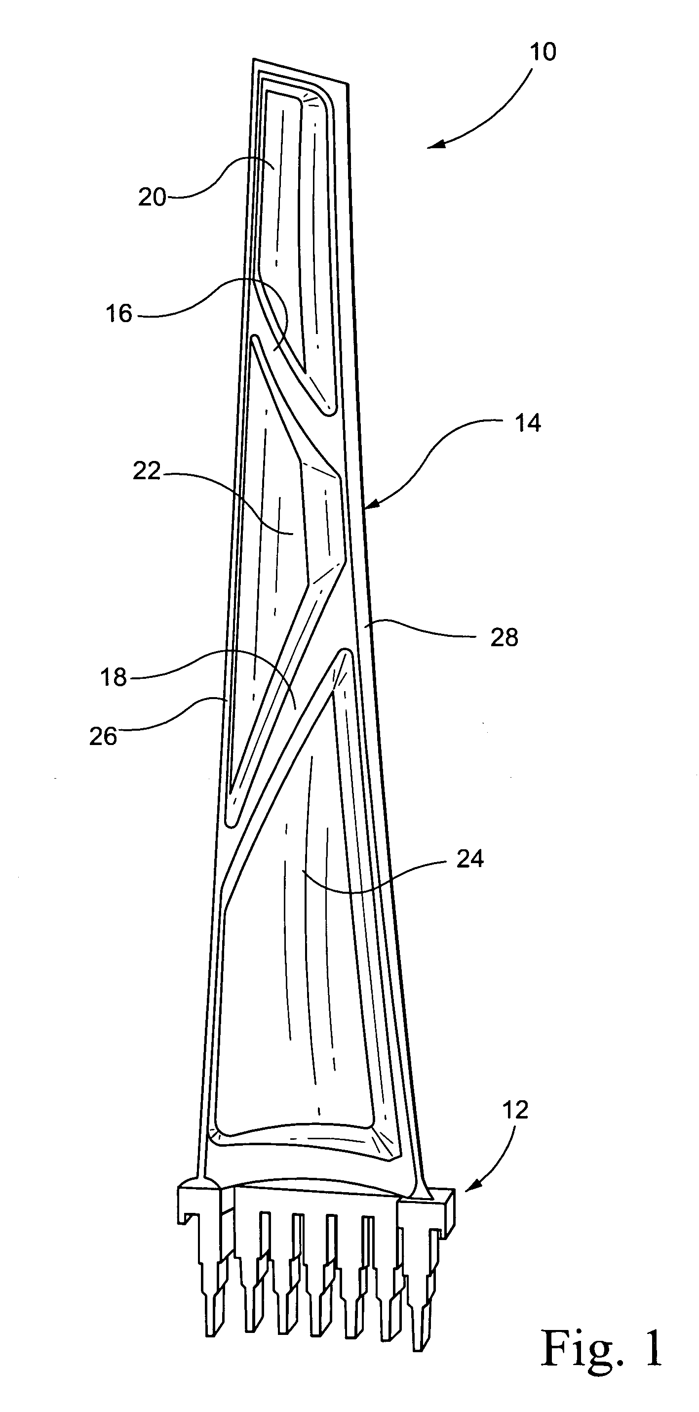
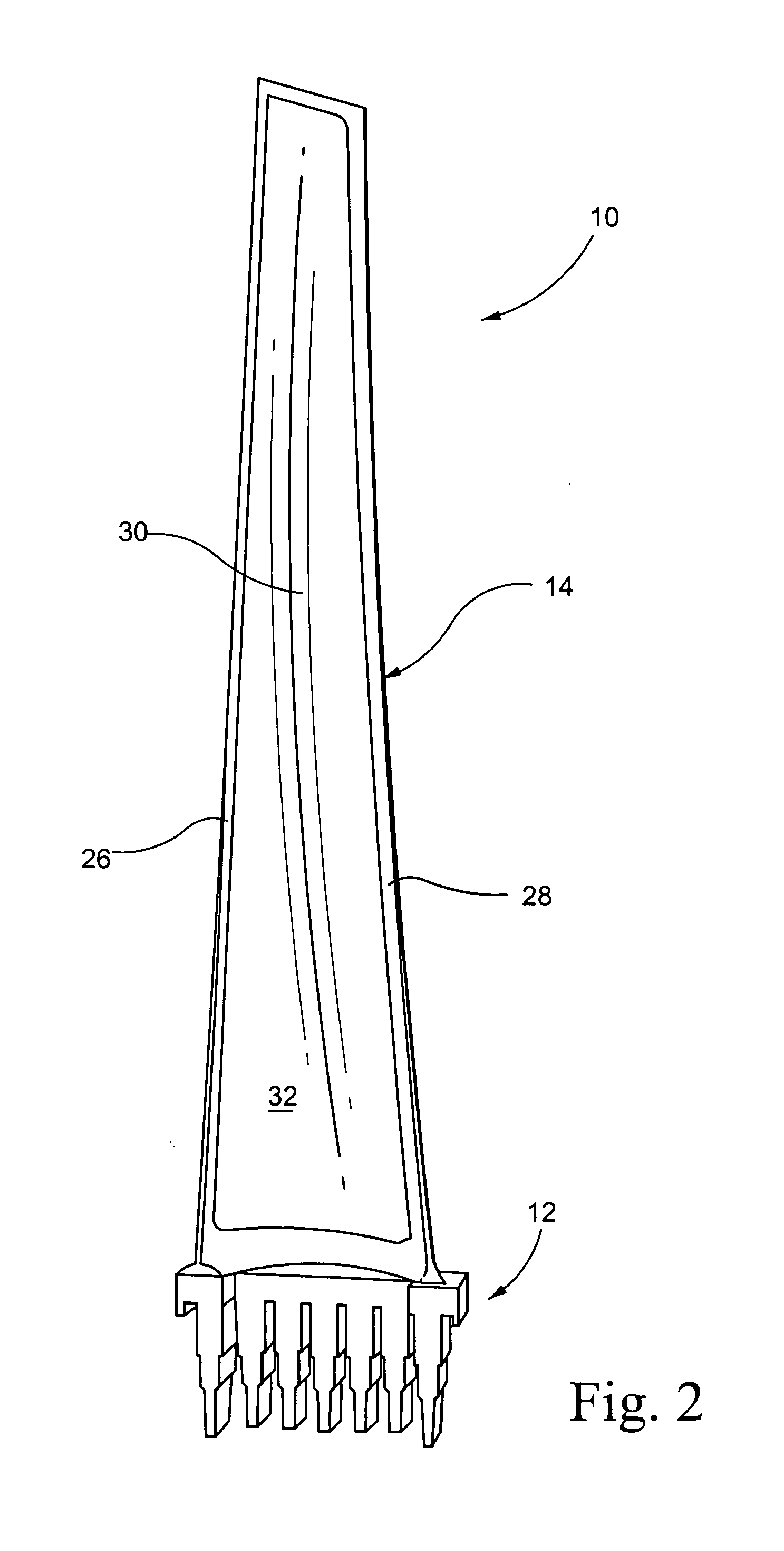
[0021] With reference to FIG. 1, a steam turbine blade 10 is shown in partially manufactured form. The blade 10 includes a shank portion 12 and an airfoil portion 14. This invention is especially concerned with the airfoil portion 14 that is preferably constructed of steel or titanium but other suitable materials include aluminum, cobalt or nickel. Ribs 16, 18 are integrally cast with the airfoil portion to form discrete filler pockets (or simply, pockets) 20, 22 and 24. It will be appreciated, however, that the ribs do not extend flush with the side edges 26, 28 of the airfoil portion. In one example, a polymer (urethane)-based filler material 30 is cast-in-place over the pressure (or suction) side of the airfoil, filling the pockets 20, 22 and 24 and covering the ribs to thereby form a smooth polymer face 32 over the entire pressure side of the blade, as shown in FIG. 2. It is also within the scope of the invention to have the ribs or surfaces defining the individual pockets to be...


PUM


Abstract

A steam turbine blade includes a shank portion and an airfoil portion. The airfoil portion is formed with at least one pocket filled with a polymer filler material chosen as a function of natural frequency impact on the turbine blade or as a function of the damping characteristics of the filler materials. A steam turbine rotor wheel includes a plurality of blades secured about a circumferential periphery of the wheel, each blade having one or more pockets in the airfoil portion, the plurality of blades divided into two groups of blades. The pockets of one group of blades are filled with one or more polymer filler materials, and the pockets of the other group of blades filled with one or more polymer filler materials, wherein the polymer filler materials in the one group of blades creates different natural frequencies or damping characteristics in the blades of the one group than the polymer filler materials in the blades of the other group. The two groups of blades are assembled on the rotor wheel in accordance with a predetermined pattern.

Description

BACKGROUND OF THE INVENTION [0001] This invention relates generally to steam turbine buckets (or blades) and, more particularly, to hybrid composite blades specifically designed to provide different predetermined material frequency and / or damping characteristics for improved system performance. [0002] Steam turbine blades operate in an environment where they are subject to high centrifugal loads and vibratory stresses. Vibratory stresses increase when blade natural frequencies become in resonance with running speed or other passing frequencies (upstream bucket or nozzle count, or other major per / rev features). The magnitude of vibratory stresses when a blade vibrates in resonance is proportional to the amount of damping present in the system (damping is comprised of material, aerodynamic and mechanical components, as well as the vibration stimulus level). For continuously coupled blades, the frequency of vibration is a function of the entire system of blades in a row, and not necess...

Claims


Application Information

Patent Timeline
IPC IPC(8): B64C27/46F01D5/14F01D5/16
CPCF01D5/147Y10S416/50F05D2300/43F01D5/16Y02T50/60F01D5/14F01D5/12F05D2260/961
Inventor BURDGICK, STEVEN SEBASTIANDELEONARDO, GUY W.LIN, WENDY W.BARB, KEVIN JOSEPH
Owner GENERAL ELECTRIC CO
Why Eureka
Try Eureka