Operation control of a fuel cell system

a fuel cell and control technology, applied in the direction of fuel cells, electrochemical generators, electrical equipment, etc., can solve the problems of clogging of oxidizing gas pipelines, inability to discharge formed water, interference of oxidizing gas supply, etc., to achieve water discharge efficiently and simplify the device arrangement

Inactive Publication Date: 2006-02-09
TOYOTA JIDOSHA KK
View PDF3 Cites 17 Cited by
  • Summary
  • Abstract
  • Description
  • Claims
  • Application Information

AI Technical Summary

Benefits of technology

[0014] When the outlet gas pressure is lowered without limit, this invites a decrease of the inlet gas pressure together with time, and thus, there is a possibility of inviting insufficient supply of oxidizing gas. To suppress this disadvantage, it is also possible to place a limit of performing the decrease in the outlet gas pressure for the present invention under the restriction of maintaining the inlet gas pressure of the oxygen electrode at a specified value or higher. In this way, the inlet gas pressure is maintained at a specified value for which it is possible to realize a suitable supply of oxidizing gas, so it is possible to operate the fuel cell with stability. This control, for example, can be realized by prohibiting a decrease in the outlet gas pressure at a point in time at which it is determined that the inlet gas pressure is lower than the specified value.
[0015] With the present invention, it is possible to provide t...

Problems solved by technology

When a large amount of water is formed by the reaction, there is a case to be impossible to discharge the formed water and the formed water causes clogging of oxidizing gas piping depending on the fuel cell operating condition.
This phenomenon called flooding causes interference of oxidizing gas supply to the oxygen electrode.
By the interference, the performance of the electricity generation becomes lower and an adverse effect such as shortening of the fuel cell lifetime may occur.
Increase of t...

Method used


Image

  • Operation control of a fuel cell system
  • Operation control of a fuel cell system
  • Operation control of a fuel cell system

Examples


Embodiment Construction

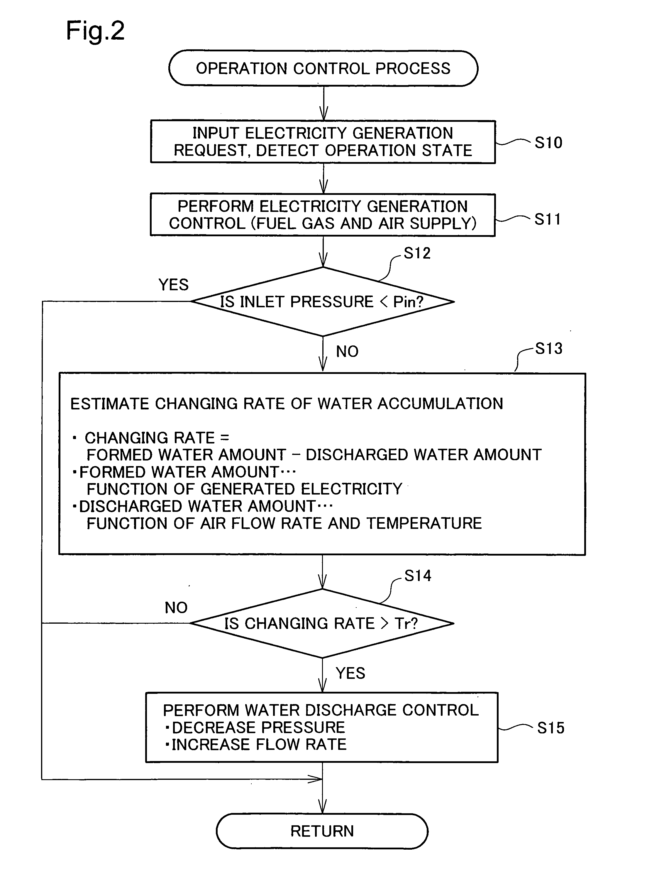
[0020] The embodiments of the present invention are described in the following order. [0021] A. Device Arrangement: [0022] B. Operation Control Process: [0023] C. Water Discharge Control: [0024] D. Variation Example:

A. Device Arrangement:

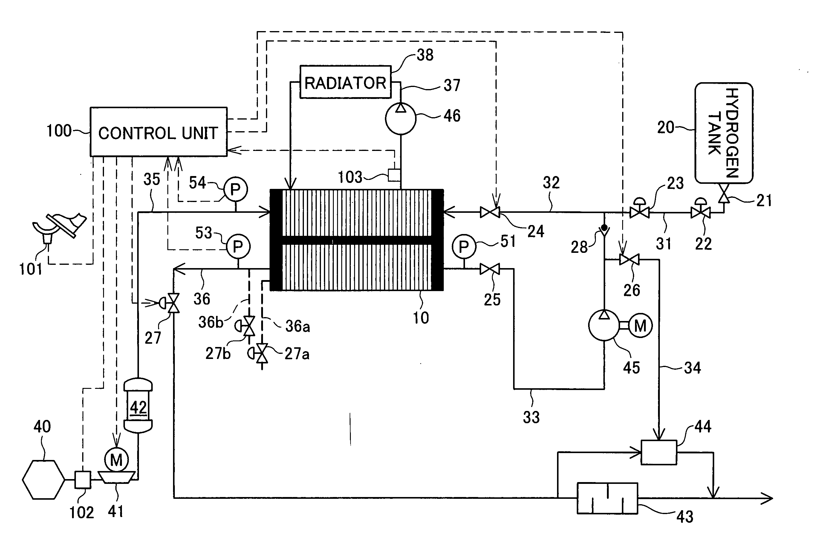
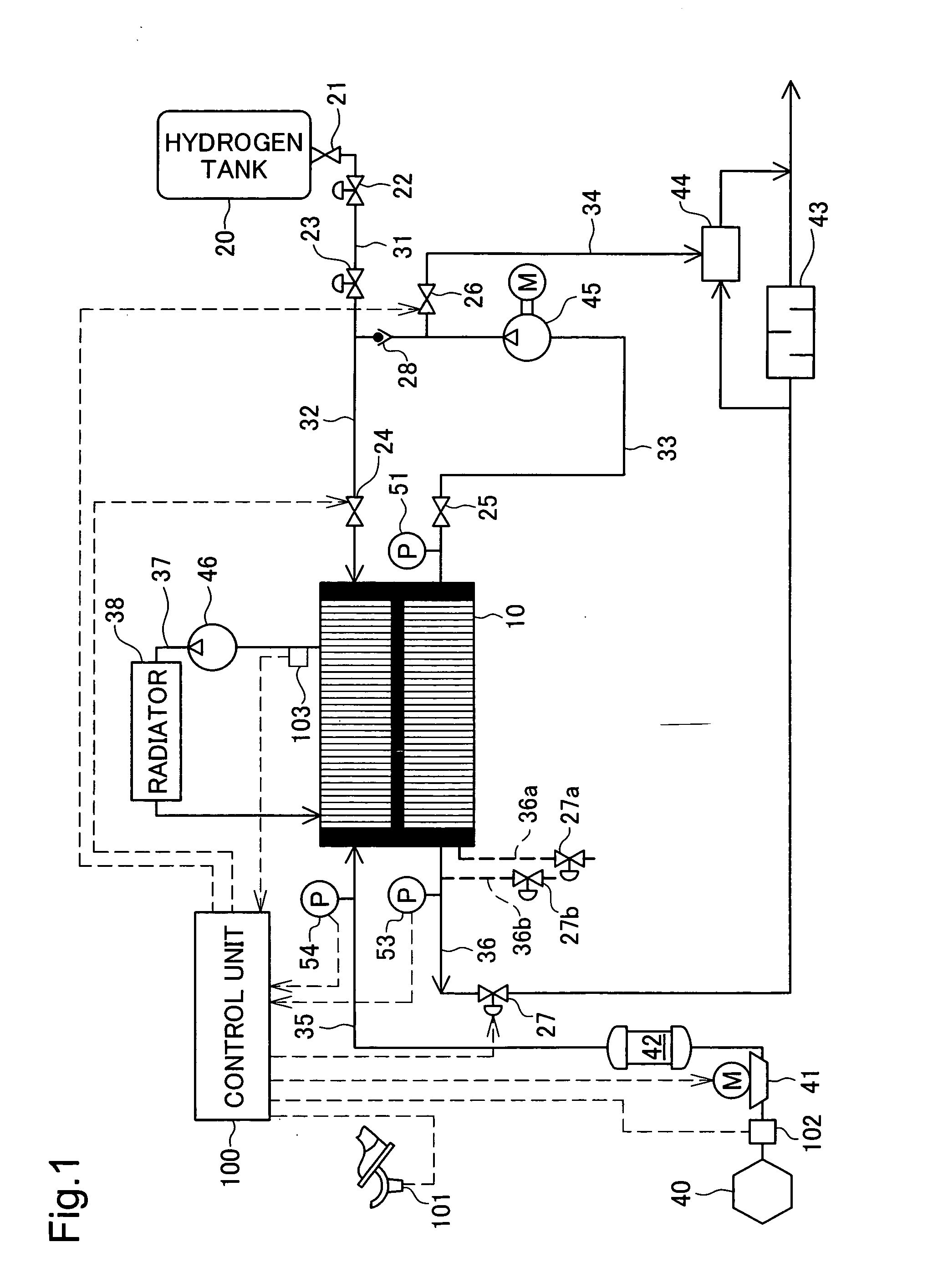
[0025]FIG. 1 is an explanatory drawing showing the overall arrangement of the fuel cell system as an embodiment. The fuel cell system in this embodiment is incorporated in an electric vehicle driven by a motor as a power source. When the driver depresses the accelerator, power generation is performed according to the depression amount detected by the accelerator opening sensor 101, and it is possible to run the vehicle using this power. The fuel cell system does not have to be placed within the vehicle as this embodiment. The present invention may be applicable for the fuel cell systems with various arrangements such as the stationary type fuel cell system.

[0026] The fuel cell stack 10 is a stack of cells for generating electricity by an electro...


PUM


Abstract

For a fuel cell system, the flow rate and the pressure of the air flow supplied to the cathode side are controlled with the following procedure. First, air is supplied to the cathode at the flow rate and supply pressure required for generating electricity. In this state, the changing rate of the amount of formed water accumulated in the cathode is estimated based on the required electricity generation and the air flow rate. When the accumulated amount of formed water increases in a high rate, to avoid flooding, the cathode outlet regulation valve is intermittently opened to decrease the outlet gas pressure. Also, at a frequency less than that of the pressure decrease, the air flow rate is increased. By executing this operation, the increased air flow rate and the pressure difference between the cathode inlet and outlet, it is possible to promote discharge of the formed water with small loss of energy.

Description

[0001] This is a Continuation of Application No. PCT / JP2004 / 005524 filed Apr. 16, 2004, which claims benefit of Japanese Patent Application No. 2003-138260 filed May 16, 2003. The entire disclosure of the prior applications is hereby incorporated by reference herein in its entirety.TECHNICAL FIELD [0002] The present invention relates to the operation control of a fuel cell system for generating electricity by an electrochemical reaction of hydrogen and oxygen. BACKGROUND ART [0003] In recent years, fuel cell for generating electricity by an electrochemical reaction between hydrogen and oxygen has been focused on as an energy source. The fuel cell is configured with a hydrogen electrode and an oxygen electrode sandwiching an electrolyte. When hydrogen-rich fuel gas is supplied to the hydrogen electrode and oxidizing gas such as air is supplied to the oxygen electrode, the hydrogen and oxygen in these gases react to form water while generating electricity. This reaction mainly occurs ...

Claims


Application Information

Patent Timeline
IPC IPC(8): H01M8/04H01M8/06
CPCH01M8/04089Y02E60/50H01M8/04156
Inventor YUMITA, OSAMUMIZUNO, KEIZOU
Owner TOYOTA JIDOSHA KK
Why Eureka
Try Eureka