High strength composite wall panel system

a composite wall and panel technology, applied in the field of high-performance composite wall structures, can solve the problems of poor k value of concrete, little or no structural strength, and little thermal insulation, and achieve the effect of improving, being stronger and less expensiv

Inactive Publication Date: 2006-02-16
OWENS CORNING INTELLECTUAL CAPITAL LLC
View PDF27 Cites 28 Cited by
  • Summary
  • Abstract
  • Description
  • Claims
  • Application Information

AI Technical Summary

Benefits of technology

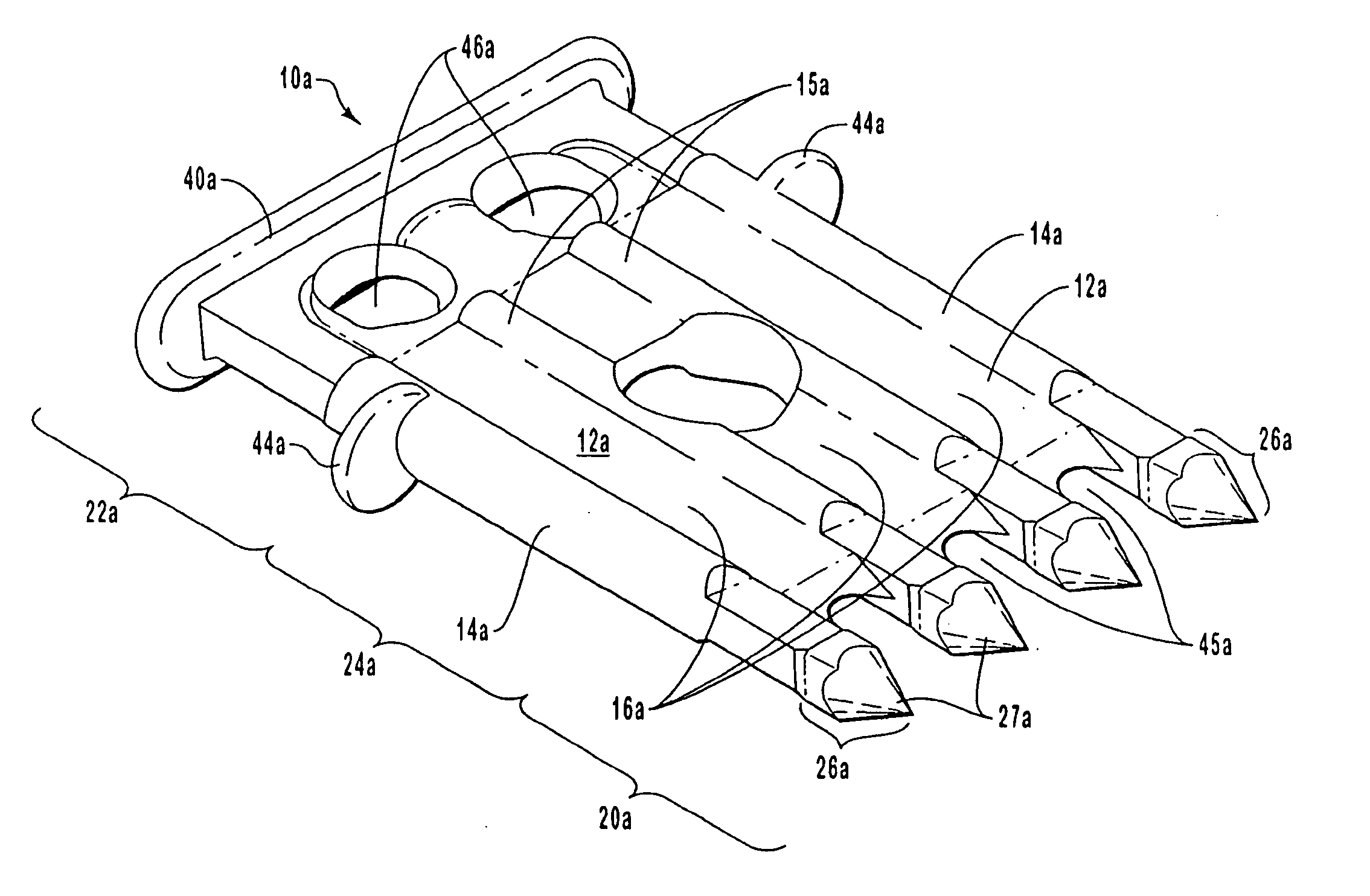
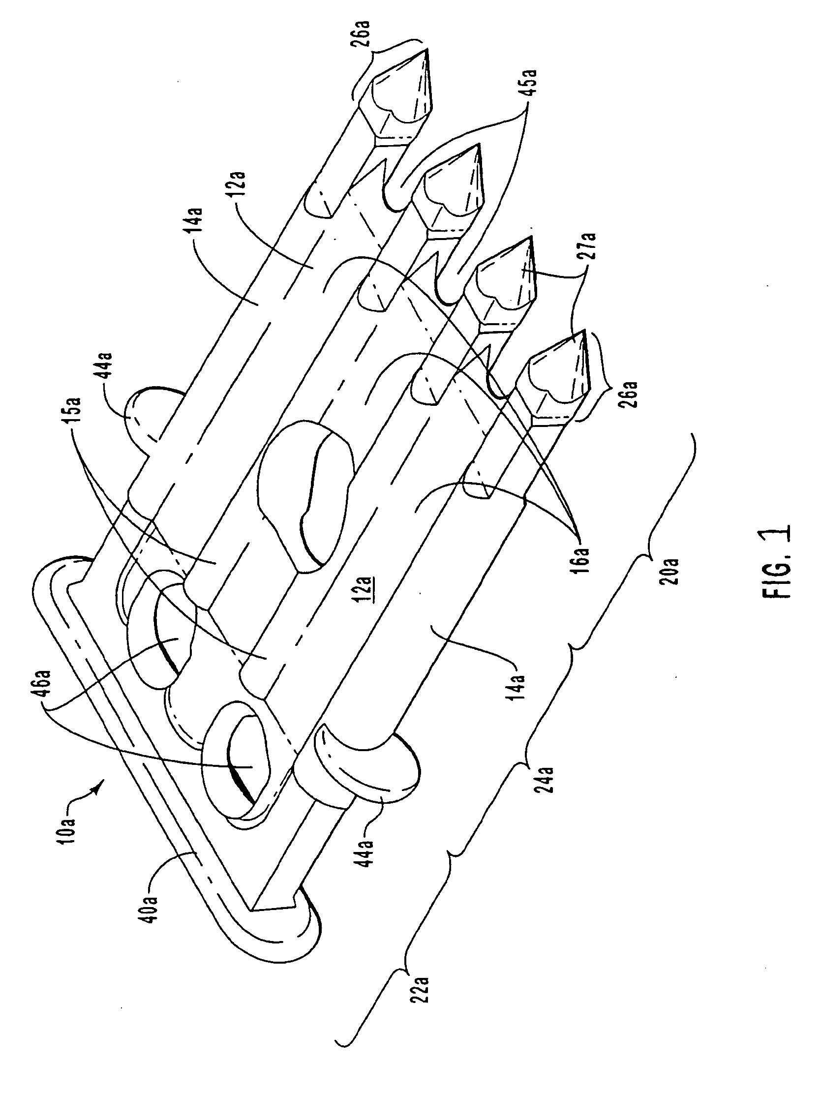
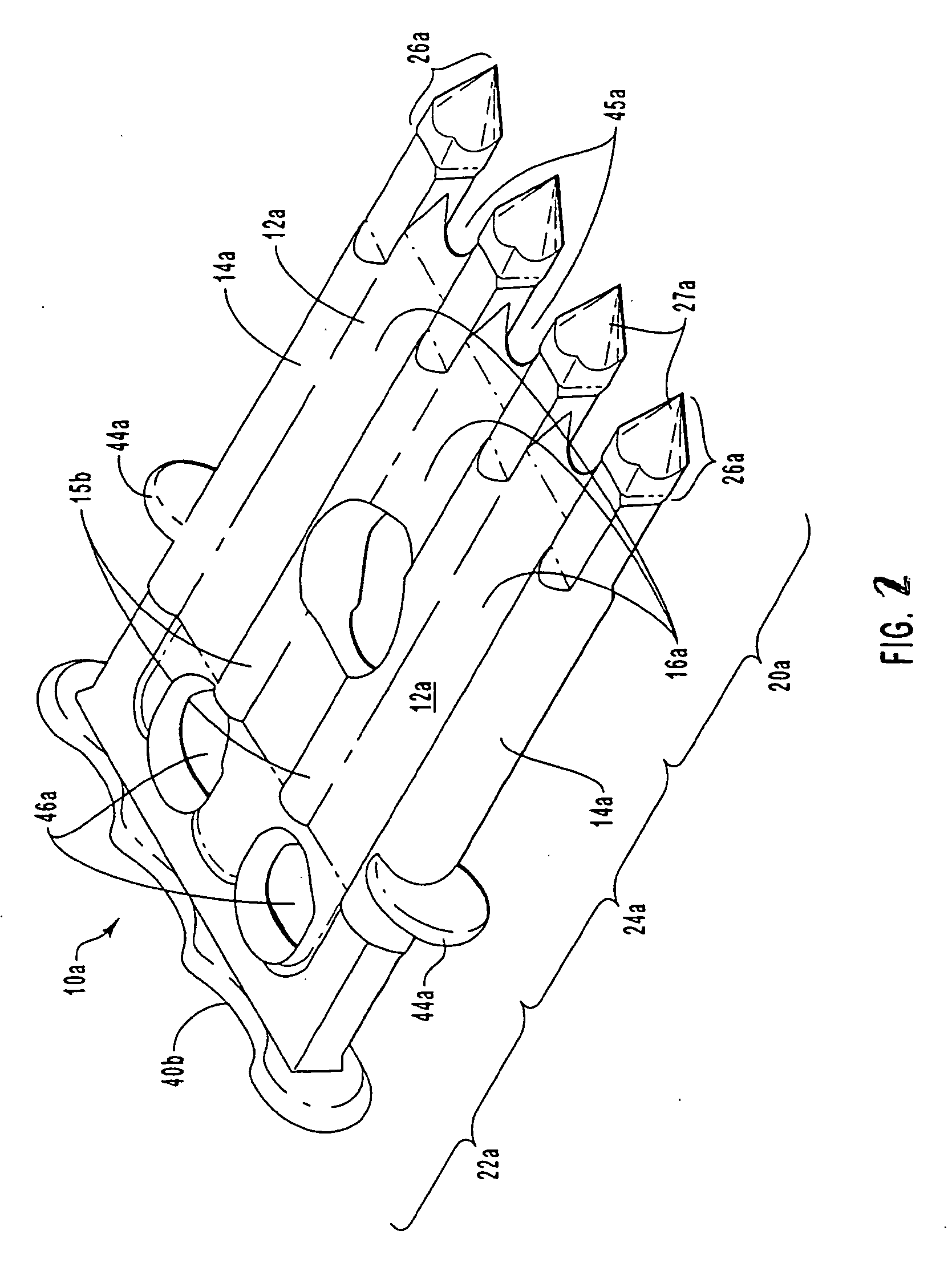
[0010] The present invention is directed to improved composite action walls having an insulation wythe sandwiched between structural wythes. The structural wythes provide the load-bearing function and prevent the collapse of the wall under high wind loads. The structural wythes demonstrate composite action existing between the structural wythes such that an improved, stronger and less expensive wall may be constructed. The present invention is also directed to an insulation wythe, which is useful in the composite action wall of the present invention, having grooves formed therein such that the material of the structural wythes flow into the groove to form a mechanical bond between the structural wythes and the insulation wythe.

Problems solved by technology

Unfortunately, concrete has the drawback of offering a poor K value and thus provides little thermal insulation.
Polystyrene and fiberglass provide a high R value but offer little or no structural strength.
The R-value of insulated two wythe walls is limited due to the structural bridging between the outer and inner wall.
The plastic tie is used in the construction industry, but is relatively expensive and difficult to manufacture and does not provide adequate composite action.
Existing connectors, however, have thus far proven inadequate for providing composite walls with the desired composite action.
The fascia wythe is typically not used to bear a load separated from the structural wythe because of insufficient composite action existing between the facia wythe and the structural wythe.

Method used


Image

  • High strength composite wall panel system
  • High strength composite wall panel system
  • High strength composite wall panel system

Examples


examples

[0060] Three structural panels, each having two wythes of concrete and an internal wythe of polystyrene foam insulation were prepared for testing. The concrete wythes were 3 in thick and the polystyrene layer was 2 in. thick. The polystyrene foam was FOAMULAR F250 (available from Owens Coming of Toledo, Ohio) having horizontal dovetail grooves having a depth of 0.5 in.; a base width of 1.0 in.; and a surface width of 0.75 in. The grooves were spaced along the length of the board by 6.0 in. (on center).

[0061] The finished panel was 8 in thick by 8.0 feet wide and 32.0 feet high. The panels included 144 connectors as shown in FIG. 5B in 18 rows and 6 columns. The rows were 16 inches on center apart and the connectors with in each row were 16 inches on center apart apart.

[0062] The panels were supported by a span equal to 31 feet and load tests were performed using negative air pressure to simulate uniform wind loading. The panel properties compressive strength of concrete (f′c-avg),...


PUM

PropertyMeasurementUnit
anglesaaaaaaaaaa
anglesaaaaaaaaaa
90° anglesaaaaaaaaaa

Abstract

The present invention is directed to improved composite action walls having an insulation wythe sandwiched between structural wythes. The structural wythes provide the load-bearing function and prevent the collapse of the wall under high wind loads. The structural wythes demonstrate composite action existing between the structural wythes such that an improved, stronger and less expensive wall may be constructed. The present invention is also directed to an insulation wythe, which is useful in the composite action wall of the present invention, having grooves formed therein such that the material of the structural wythes flow into the groove to form a mechanical bond between the structural wythes and the insulation wythe. The walls of the present invention are simple to manufacture and provide a verifiable and consistent composite action between about 50% to about 100% composite action.

Description

TECHNICAL FIELD AND INDUSTRIAL APPLICABILITY OF THE INVENTION [0001] The present invention relates to the field of concrete wall structures and, more specifically, to the field of high composite action wall structures. BACKGROUND OF THE INVENTION [0002] In the area of building and construction, concrete wall panels have been fabricated and then coated or layered with insulation having relatively low strength to provide a well-insulated wall structure having high strength. Typically, a structural wall is built and insulation is applied when finishing the wall. The insulation inhibits the flow of thermal energy through the wall. [0003] A commonly used measurement of the thermal insulating qualities of a material is the mathematical coefficient “R”, which is a measure of the thermal resistance of a material. The coefficient R is equal to the thickness divided by the thermal coefficient “K”. A high R value provides a high degree of high thermal resistance or insulating ability. [0004] C...

Claims


Application Information

Patent Timeline
Patent Type & Authority Applications(United States)
IPC IPC(8): E04C1/00
CPCB29C44/1214E04C2002/047B32B3/30B32B5/18B32B13/00B32B13/045B32B13/12B32B2250/03B32B2250/40B32B2266/0228B32B2266/025B32B2266/0278B32B2307/304B32B2307/536B32B2307/54B32B2307/542B32B2419/04B32B2607/00E04B2001/4192E04C2/044E04C2/288B32B3/10
Inventor DEVALAPURA, RAVI K.
Owner OWENS CORNING INTELLECTUAL CAPITAL LLC
Why Eureka
Try Eureka