Ribbed steel engraved mesh for cast-in-place cavity floor

A technology of cavity floor and steel mesh, which is applied to floors, structural elements, building components, etc.

Inactive Publication Date: 2016-03-23
王本淼 +2
View PDF9 Cites 27 Cited by
  • Summary
  • Abstract
  • Description
  • Claims
  • Application Information

AI Technical Summary

Problems solved by technology

Ribbed steel mesh is used to realize the new technology of forming holes in the cast-in-place cavity floor, and the unsealed ribbed steel mesh is used to replace the existing fully sealed hollow filling body or polystyrene foam solid filling body, optimizing the existing cast-in-place cavity Hole-forming technology of cavity floor, overcomes the defects existing in existing cavity-floor hole-forming technology

Method used


Image

  • Ribbed steel engraved mesh for cast-in-place cavity floor
  • Ribbed steel engraved mesh for cast-in-place cavity floor
  • Ribbed steel engraved mesh for cast-in-place cavity floor

Examples


Embodiment Construction

[0025] The invention will be further described below in conjunction with the accompanying drawings.

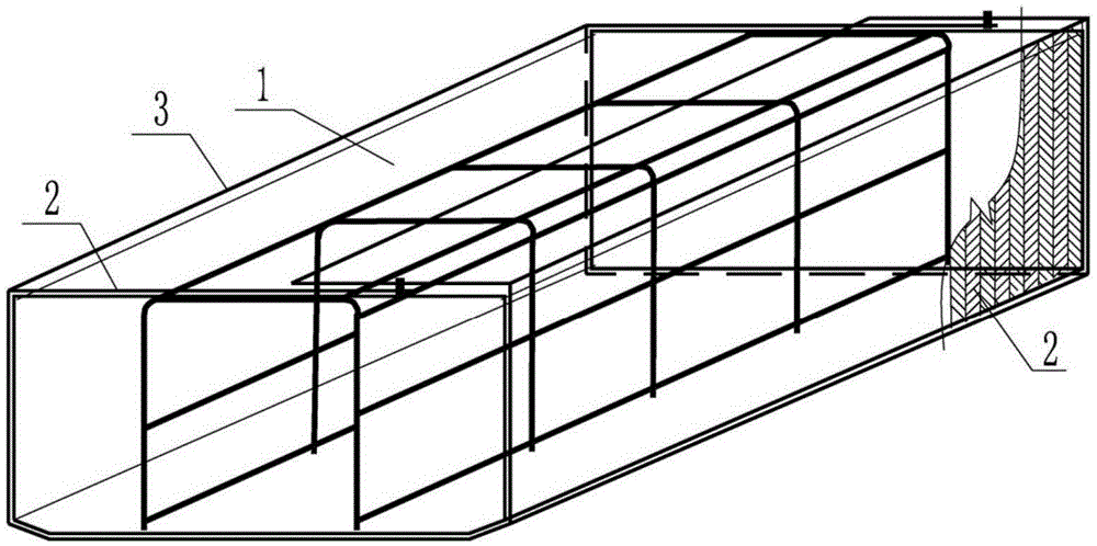
[0026] figure 1 It is the folded diagram of the ribbed stencil in the first embodiment of the present invention, such as figure 1 As shown, special mechanical equipment such as unwinding machine, punching machine system, expansion system, and shearing machine will be used to make expanded metal mesh body and press the mesh 2 with bending marks 3. The main body of the mesh 2 around the ribbed steel mesh hole 1 is bent one by one at the marks.

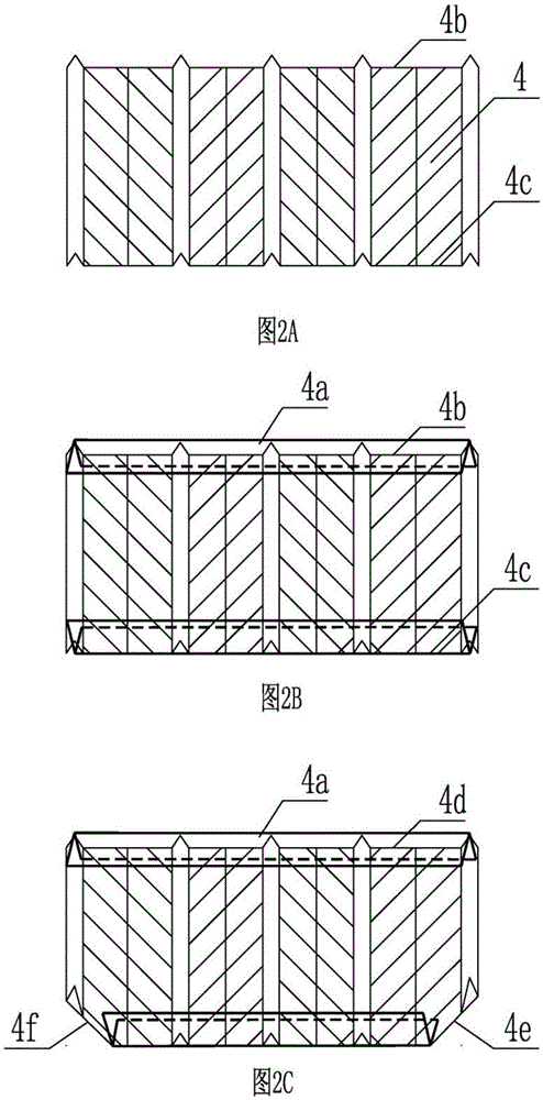
[0027] figure 2 It is the ribbed steel mesh openwork end mesh structure of the second embodiment of the present invention figure 2 A. figure 2 B, such as figure 2 As shown in A, the factory cuts the length of the required end mesh 4 steel mesh body according to the height of the ribbed steel mesh. Use special equipment to press the thin steel sheet 4a into a V shape, wrap the two ends of the end mesh 4, and then use a punching ...


PUM

PropertyMeasurementUnit
heightaaaaaaaaaa
lengthaaaaaaaaaa
thicknessaaaaaaaaaa

Abstract

The invention provides a ribbed steel engraved mesh for a cast-in-place cavity floor. The ribbed steel engraved mesh is composed of an engraved mesh, a supporting mesh and an engraved end mesh; the engraved mesh, the supporting mesh and the engraved end mesh all are made of a pure metal material; the engraved mesh forms a periphery of the ribbed steel engraved mesh; the engraved end mesh closes the ribbed steel engraved mesh and the supporting engraved mesh to form an engraved end section shape of the ribbed steel engraved mesh; the supporting mesh controls a height of an internal space of the ribbed steel engraved mesh; the engraved mesh and the engraved end mesh are fabricated from steel mesh bodies, and each steel mesh body comprises steel sheet dilated mesh holes, a V-shaped rib and a steering connecting piece; the dilated mesh holes on two sides of the steering connecting pieces are not in the same direction; the V-shaped rib is greater than 6mm high; at least four measuring fixed marks are formed by pressing on the V-shaped rib of the steel mesh body of the engraved mesh in a vertical direction; and the supporting mesh is a steel mesh body or a reinforcing mesh body; the ribbed steel engraved mesh is used for casting the cavity floor, and the ribbed steel engraved mesh is directly buried in concrete cast in place at edges of a cavity to achieve a suppression effect on temperature cracks of the floor.

Description

technical field [0001] The invention relates to a non-centering hole-forming technology for a cast-in-place cavity floor, in particular to a ribbed steel mesh for a cast-in-place cavity floor. Background technique [0002] At present, in the technical field of cast-in-place reinforced concrete hollow floors, a fully sealed filling member is usually used to form a hollow floor, such as the ZL98231113.3 concrete thin-walled cylindrical member declared by the inventor, which is made into a sealed cylindrical filling body. In order to realize the cast-in-place hollow floor, a tubular hollow filling body is provided, which solves the technical problem of non-centering hole formation in the cast-in-place hollow floor. However, due to the sealed tubular hollow filling body, there are defects such as difficult fixing, high buoyancy, high density and heavy weight, inconvenient production, transportation and on-site construction, low evacuation rate, and inability to form a large-scal...

Claims


Application Information

Patent Timeline
Patent Type & Authority Applications(China)
IPC IPC(8): E04C5/06E04B5/36
CPCE04C5/0627E04B5/36
Inventor 王本淼王海崴马锋
Owner 王本淼
Why Eureka
Try Eureka