Air conditioning apparatus

Inactive Publication Date: 2006-02-16
TOYOTA JIDOSHA KK
View PDF7 Cites 65 Cited by
  • Summary
  • Abstract
  • Description
  • Claims
  • Application Information

AI Technical Summary

Benefits of technology

[0011] In the first heat exchanger, the flow passage which the first heating medium flows through, and the flow passage which the second heating medium flows through, are formed adjacent to and in parallel with each other, and the flowing directions of each heating medium can be made opposite to each other. With this construction, heat transfer efficiency between the heating mediums can be improved.
[0012] The third heat exchanger can be constructed of a heat storing device having a heat

Problems solved by technology

This makes it probable that necessary air

Method used


Image

  • Air conditioning apparatus
  • Air conditioning apparatus
  • Air conditioning apparatus

Examples


Embodiment Construction

[0041] This invention will be described with reference to the accompanying drawings.

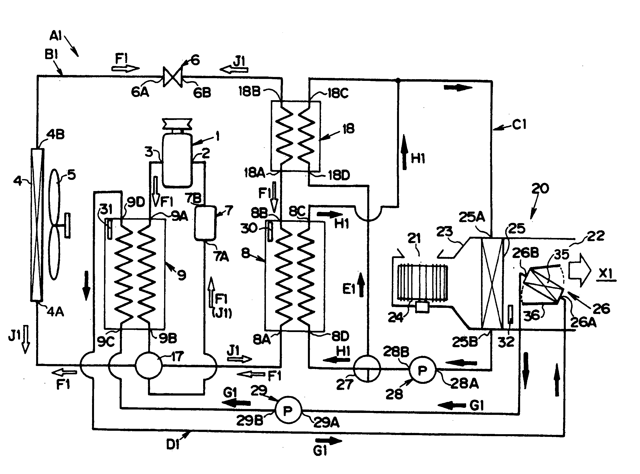
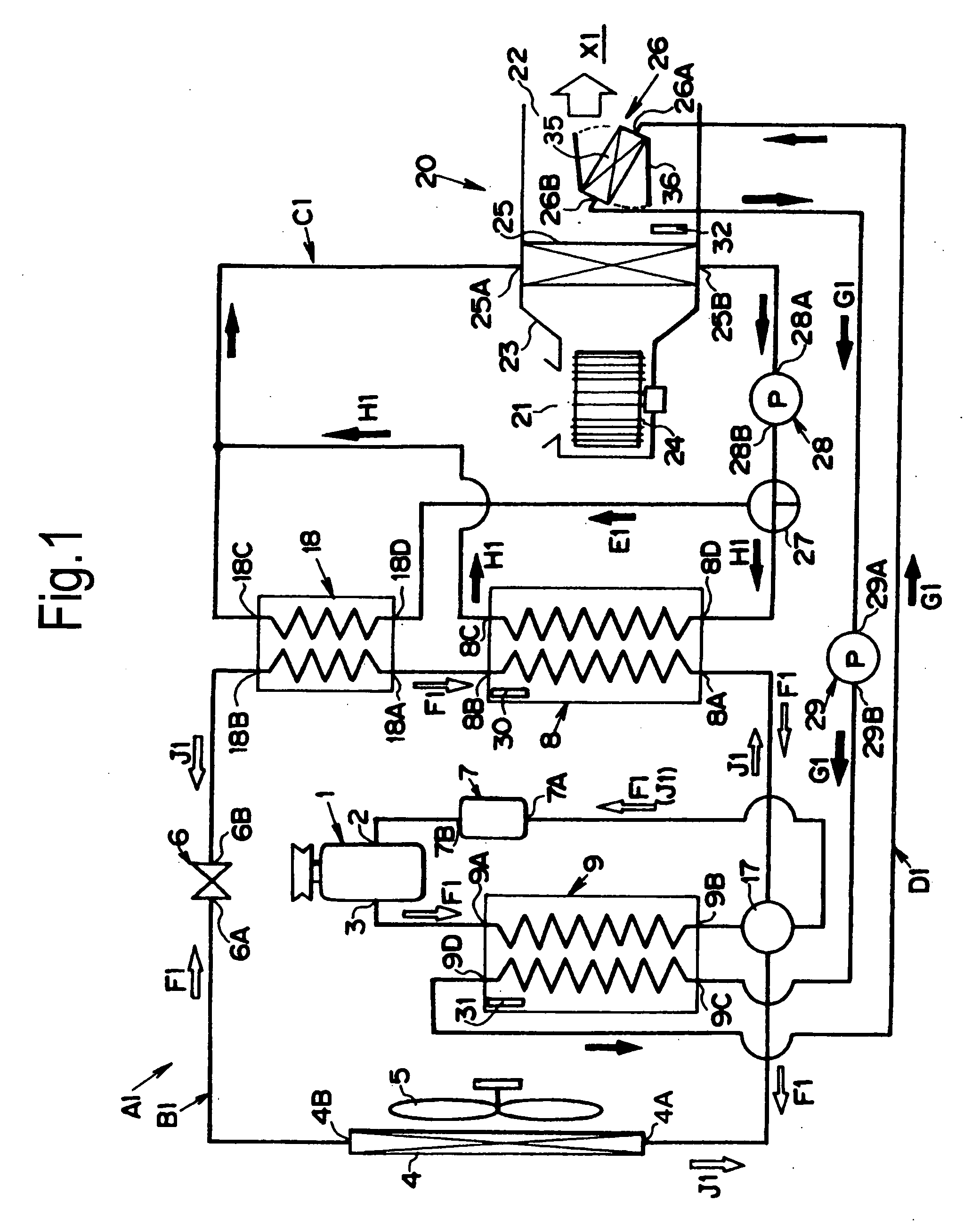
[0042]FIG. 1 is a conceptional diagram showing a construction of an air conditioning system A1 for a vehicle. The air conditioning system A1 has a first circuit B1, a second circuit C1 and a third circuit D1. Each circulation circuit is, specifically, a flow passage for a fluid having a piping. A refrigerant (e.g., chlorofluorocarbon or refrigerant gas containing no chlorine) flows through the first circuit B1, whereas a brine (e.g., water or saltwater) flows through the second circuit C1 and the third circuit D1.

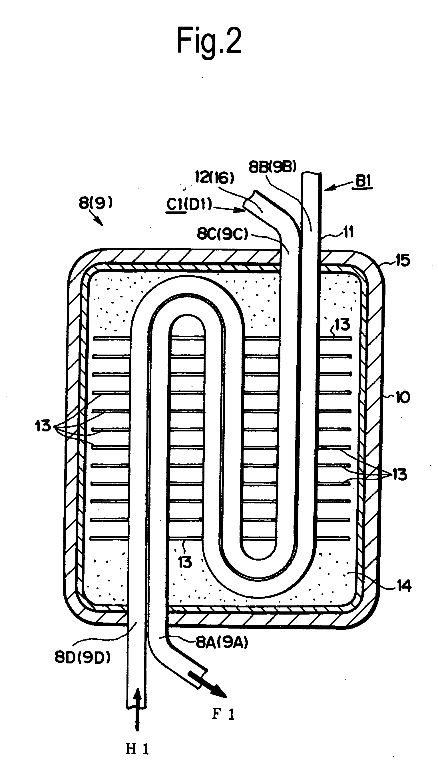
[0043] A construction of the first circuit B1 will be described first. A compressor 1 is arranged in the first circuit B1, which has a suction port 2 and a discharging port 3. The compressor 1 is driven by an (later-described) engine or an (later-described) electric motor. On the other hand, an outdoor heat exchanger 4 is arranged in the first circuit B1. This outdoor heat exchanger 4 is e...


PUM


Abstract

An air conditioning system for cooling or heating an air, and for feeding the heated or cooled air to predetermined portions is characterized by comprising: a first circulating circuit for circulating a first heating medium; a second circulating circuit for circulating a second heating medium; a control unit for controlling the heat for executing heat exchange between the first heating medium and the second heating medium to flow through either the heat exchanger or the first heat storing device. Moreover, an air temperature is controlled by heat of the second heating medium.

Description

TECHNICAL FIELD [0001] This invention relates to an air conditioning system for executing a heat exchange among a plurality of heating mediums, thereby controlling air temperature on the basis of the exchanged heat. BACKGROUND ART [0002] An air conditioning system for a vehicle is generally constructed to regulate a room temperature by a refrigeration cycle for circulating a refrigerant. The air conditioning system of this kind is disclosed in Japanese Patent Laid-open No. 2000-142078. According to an air conditioning system for a vehicle disclosed in the Laid-open, a compressor, a condenser, a receiver, an expansion valve, an evaporator and so on are arranged in a circulating circuit of the refrigerant. In a casing of the air conditioning system, a blower fan and an evaporator are arranged. Moreover, an air inlet and an air outlet are formed on the casing. [0003] Here will be explained an operation example according to the aforementioned air conditioning system. First of all, when ...

Claims


Application Information

Patent Timeline
IPC IPC(8): B60H1/00B60H1/22B60H1/32F25B13/00F25B25/00F25B27/00F25B40/04F25B47/02F28D7/00F28D9/00F28D20/00
CPCB60H1/00492Y02E60/142B60H1/3204B60H2001/00928B60H2001/00935F25B13/00F25B25/005F25B27/00F25B40/04F25B47/025F25B2313/02341F25B2313/02344F25B2327/001F25B2400/24F28D7/0016F28D9/005F28D20/00B60H1/00892B60H1/32281Y02E60/14B60H1/00885B60H1/3228
Inventor TSUBONE, KENJIAIKAWA, YASUKAZUHIJIKATA, YASUTANE
Owner TOYOTA JIDOSHA KK
Why Eureka
Try Eureka