Part-geometry independent real time closed loop weld pool temperature control system for multi-layer dmd process

Active Publication Date: 2006-02-16
DM3D TECH
View PDF24 Cites 41 Cited by
  • Summary
  • Abstract
  • Description
  • Claims
  • Application Information

AI Technical Summary

Benefits of technology

[0009] The present invention is directed toward a multi-layer deposition process which employs feedback control and an adaptive sys

Problems solved by technology

The increase in the size of the weld pool del

Method used


Image

  • Part-geometry independent real time closed loop weld pool temperature control system for multi-layer dmd process
  • Part-geometry independent real time closed loop weld pool temperature control system for multi-layer dmd process
  • Part-geometry independent real time closed loop weld pool temperature control system for multi-layer dmd process

Examples


Embodiment Construction

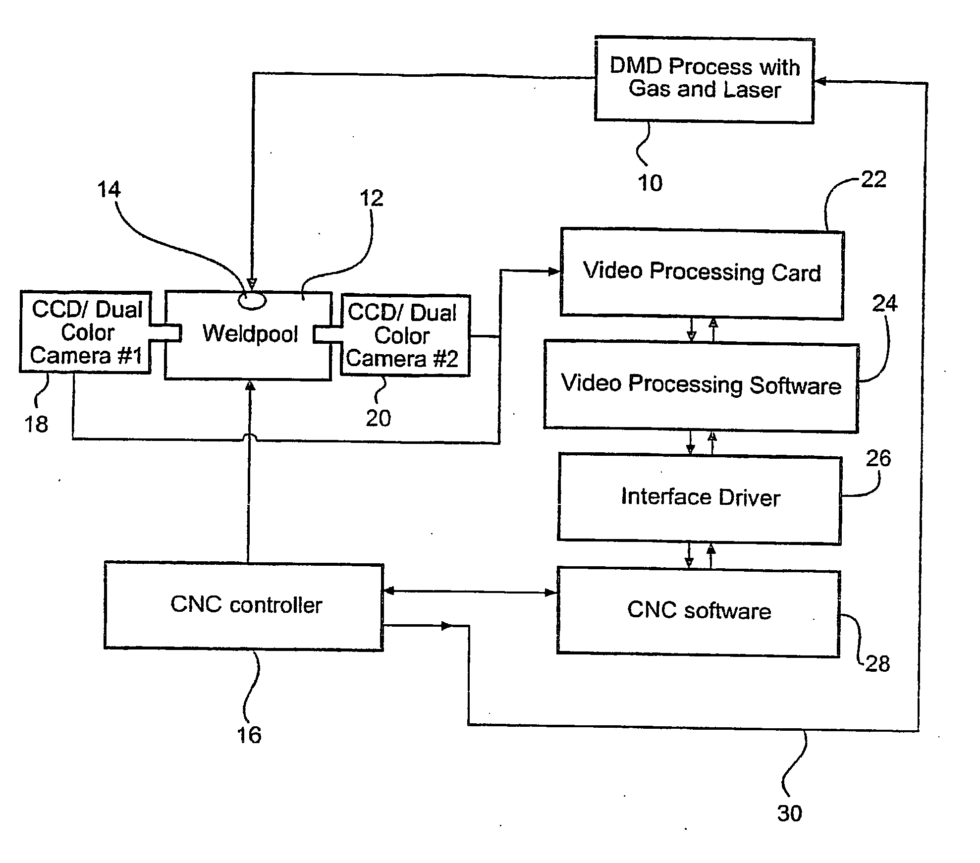
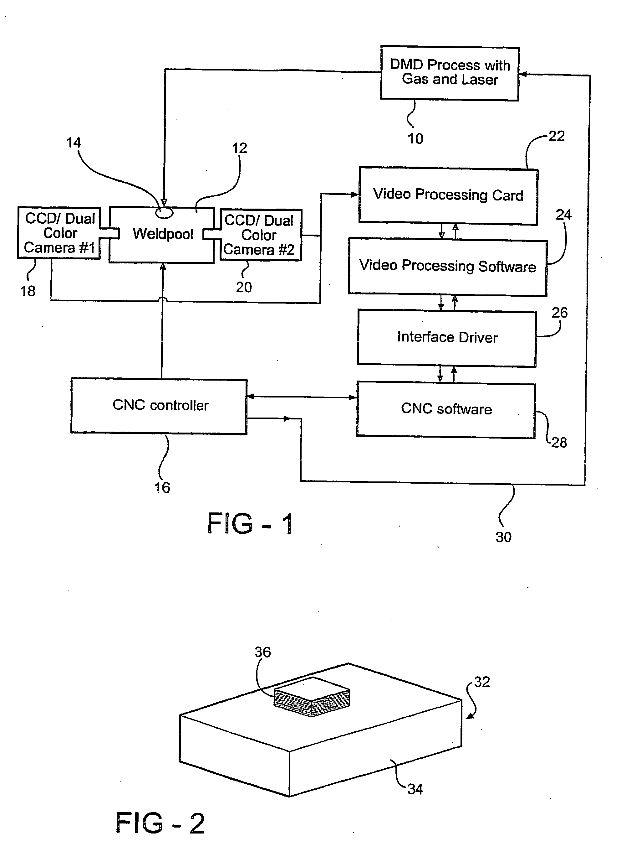
[0020] A preferred embodiment of the invention, illustrated schematically in FIG. 1, employs a head 10 consisting of a power laser and gas propelled metal powder dispenser to produce a weld pool 14 at a point on a substrate 12. This apparatus is of the type employed in the prior art such as disclosed in U.S. Pat. No. 6,122,564. Wire may be fed into the laser beam as an alternative to dispensing powder and an electron beam may be used as an alternative to the laser beam. The terms “laser” and “powder” as used hereinafter should be considered to include these alternatives.

[0021] The substrate 12 is moved relative to the head 10 by a CNC controller 16 over a programmed path so that the weld pool follows the path along the substrate so as to create a metallic layer on the substrate. A pair of CCD cameras 18 and 20 are supported on the machine worktable so as to generate images of the weld pool 14 from two opposed sides. This is necessary in case the weld pool is formed in such a way as...


PUM

PropertyMeasurementUnit
Temperatureaaaaaaaaaa
Poweraaaaaaaaaa
Dimensionaaaaaaaaaa

Abstract

In a direct metal deposition system which builds up a metallic overlay on a substrate by moving the substrate relative to a laser in a metallic powder feed, the laser power is adjusted for successive layers by sensing the weld pool in a plurality of selected points in each layer and adjusting the power during successive layers to maintain a weld pool that corresponds to those achieved during deposition of a lower optimal layer. This compensates for heating of the substrate resulting from the deposition which tends to increase the pool size or temperature in the higher layers.

Description

RELATED APPLICATION [0001] This application claims priority of U.S. Provisional Patent Application Ser. No. 60 / 406,366 filed Aug. 28, 2002, which is incorporated herein by reference.FIELD OF THE INVENTION [0002] This invention relates to the fabrication of metal parts by the direct metal deposition of a plurality of relatively thin layers on an underlying substrate, and more particularly to such a system which controls the deposition power used in forming a layer based on parameters generated during the formation of previous layers. BACKGROUND OF THE INVENTION [0003] Fabrication of three-dimensional metallic components via layer-by-layer laser cladding was first reported in 1978 by Breinan and Kear. U.S. Pat. No. 4,323,756 issued to Brown et al. in 1982, describes a method for the production of bulk rapidly solidified metallic articles of near-net shape, finding particular utility in the fabrication of certain gas turbine engine components including discs and knife-edge air seals. A...

Claims


Application Information

Patent Timeline
IPC IPC(8): B23K26/34B23K15/00B22F3/105B23K26/03B23K26/14
CPCB22F3/1055B23K15/0086B23K26/032C23C28/023B23K26/1411B23K26/3206B23K26/345B23K26/034B23K26/32B23K26/342B23K26/144B23K2103/50Y02P10/25B22F10/36B22F12/90B22F10/25B22F10/368B23K26/04
Inventor BAGAVATH-SINGH, VIJAYAVEL
Owner DM3D TECH
Why Eureka
Try Eureka