Automated level indicator for liquids container

a level indicator and automatic technology, applied in the direction of liquid/fluent solid measurement, machines/engines, instruments, etc., can solve the problems of spillage of contents on carpeting, workers are often not strong enough to supply the strength and acumen necessary, and not often realized the rough treatment of such vessels

Inactive Publication Date: 2006-02-16
WILBUR CURTIS
View PDF3 Cites 16 Cited by
  • Summary
  • Abstract
  • Description
  • Claims
  • Application Information

AI Technical Summary

Benefits of technology

[0007] An improved level indicator takes advantage of the universal visual impression of typical sight glasses, but without the disadvantages of a physical sight glass protruding from the main body of the reservoir. An improved level indicator takes advantage of the universal visual impression of typical sight glasses, but without the disadvantages of a physical sight glass protruding from the main body

Problems solved by technology

Sight glasses have always had operating limitations that the fittings securing the glass must not leak, that the fittings and glass should be able to be secured tightly enough to withstand the pressure inside the vessel.
It is not often realized the rough treatment that such vessels undergo during a typical day of usage.
Workers are often not strong enough to supply the strength and acumen necessary to treat a heavy vessel with adequate care.
A broken sight glass can result in spillage of contents on carpeting, often creating a coffee stain requiring specialized cleanup.
Breakage of sight glasses also poses a danger to nearby occupants.
Further, a rising number of incidents have been observed where the glass tubes may be intentionally broken by workers to obtain it for recreational drug use.
Sight glasses cannot effectively be protected by the use of cages and screens as they would drive up the equipment and maintenance cost significantly, as well as to obscure the visual determination of liquid level.
Cleaning and replacement would also then be a problem as any protector would require specialized cleaning and likely

Method used


Image

  • Automated level indicator for liquids container
  • Automated level indicator for liquids container
  • Automated level indicator for liquids container

Examples


Embodiment Construction

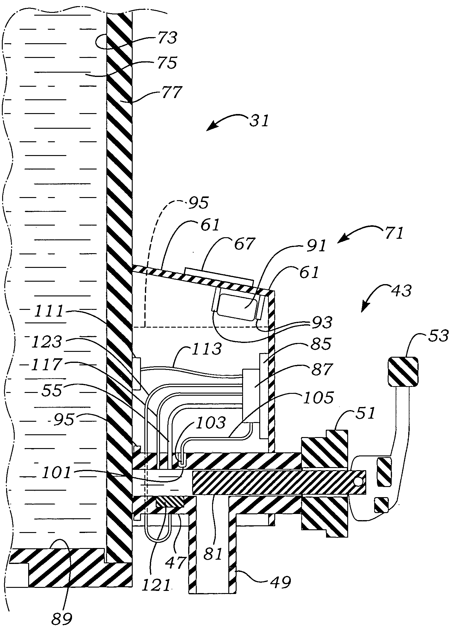
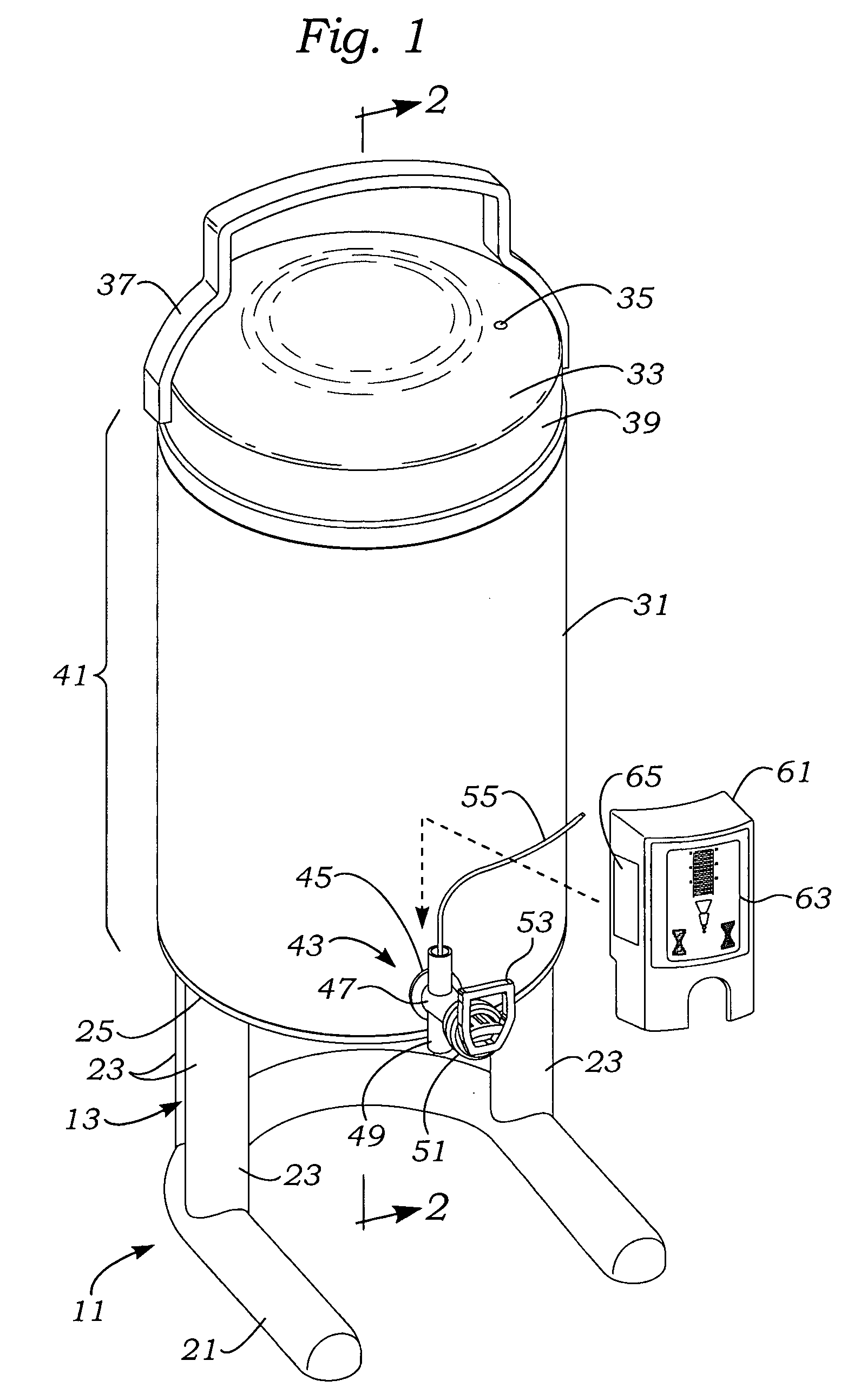
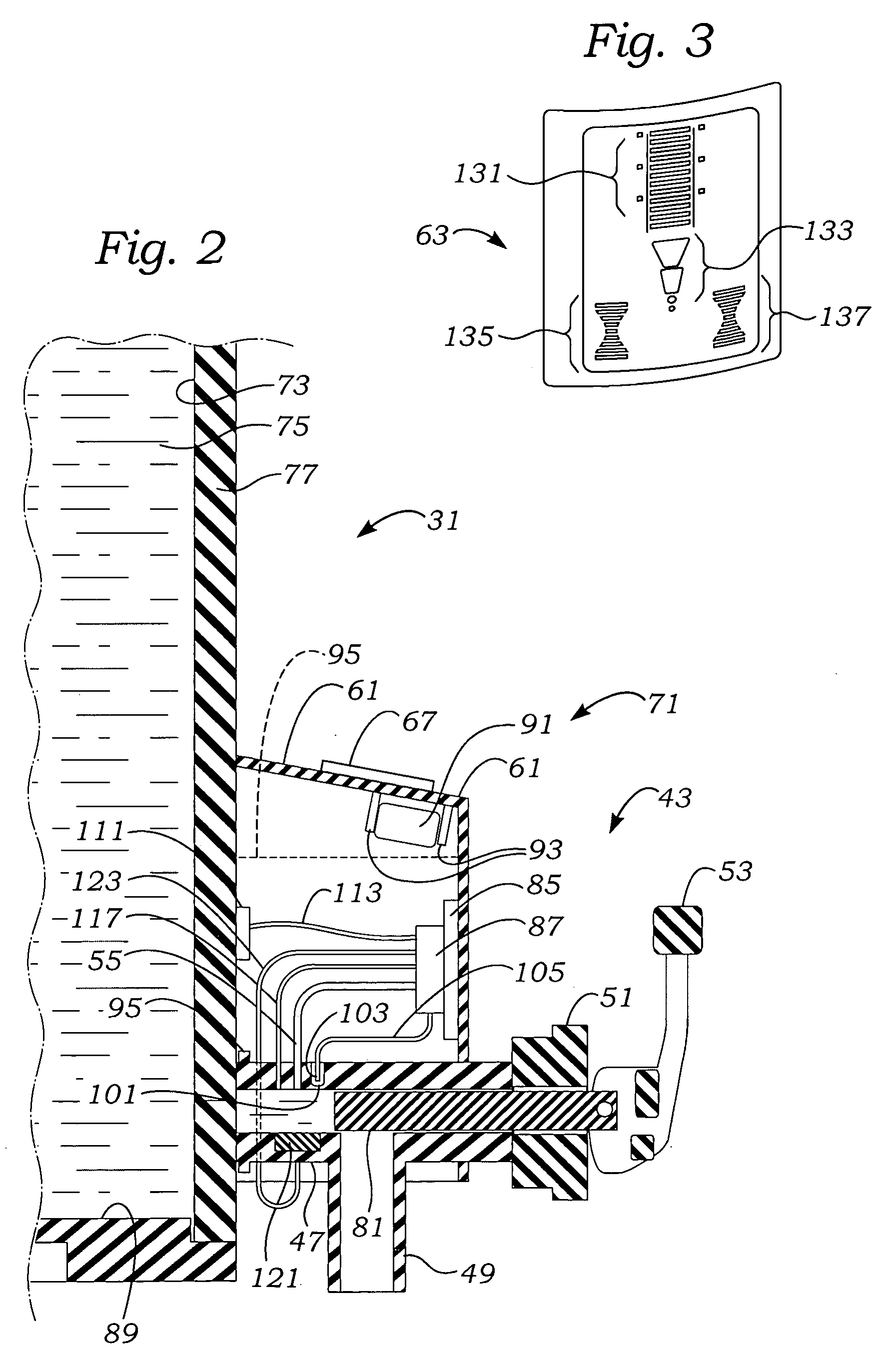
[0018] The process and apparatus described herein will in concentrate on the somewhat schematic use of a sensor in conjunction with the drain pipe of a liquid food service container upstream of the valve. Referring to FIG. 1, a generic arrangement for a food service liquid dispensing container 11 is shown as having an integrated base stand 13 which supports a vessel 15 above.

[0019] The base has a main “U” shaped support 21 to provide easy clearance for the entry of drinking cups and user access. From the main “U” shaped support 21, a series of vertical columns 23 attach to a base support 25.

[0020] A main reservoir 31 has a lid 33 with a small vent hole 35. An optional bail handle 37 is shaped to accommodate the lid 33 and folds away to enable access to the lid 33. An upper fitting 39 provides some interruption of the main cylindrical surface of the reservoir 31. A cylindrical surface 41 is generally only interrupted by a tap 43. Tap 43 in the alternative, could have emerged from b...


PUM


Abstract

An improved level indicator takes advantage of the universal visual impression of typical sight glasses, but without the disadvantages of a physical sight glass protruding from the main body of the reservoir. In addition, other quantities are measured, including two-phase presence in a drainage pipe, temperature of the liquid product measured against either the drain pipe or reservoir, and temporal passage. Each of the measured quantities can result in an individual visual indication, or can thresholded combinationally to provide a combined threshold limit for initiating visual indication. A sealed unit is provided low on a food dispensing reservoir and upstream of a dispensing valve with a sensor in fluid communication with the static pressure in the dispensing valve. Because the sealed unit is in communication with the liquid in the reservoir at the lower position only, several alternatives may be utilized to equate the static pressure with the liquid level in the food service container reservoir.

Description

FIELD OF THE INVENTION [0001] The present invention relates to the field of liquid level sensing, and more particularly to liquid level sensing for non hazardous, non-corrosive materials, and specifically to level indicators used in food service equipment. BACKGROUND OF THE INVENTION [0002] The standard for level indication equipment has for years been the sight glass. Sight glasses are visible channels, typically tubes, which share part of the volumetric capacity of a vessel and which occupy a level in the visible channel the same as the liquid inside the main vessel. Sight glasses have always had operating limitations that the fittings securing the glass must not leak, that the fittings and glass should be able to be secured tightly enough to withstand the pressure inside the vessel. [0003] Food service vessels typically utilize large round sight glasses having a lower end connected to open into the bottom and an upper end connected into the top of a main liquid reservoir. The liq...

Claims


Application Information

Patent Timeline
IPC IPC(8): G01F23/02G01F23/00
CPCG01F23/16
Inventor LYALL, LUCIAN HITE III
Owner WILBUR CURTIS
Why Eureka
Try Eureka