
Evaporative cooling for aqueous batteries

Inactive Publication Date: 2006-02-16
JONES WILLIAM E M
View PDF5 Cites 4 Cited by
  • Summary
  • Abstract
  • Description
  • Claims
  • Application Information

AI Technical Summary

Benefits of technology

[0011] The present invention provides a novel method of cooling an aqueous electrolyte battery cell by causing the evaporation of water from the electrolyte. In one form, the method includes delivering non-saturated gas to the electrolyte of the battery, contacting the non-saturated gas with the electrolyte so that water from the electrolyte evaporates and thereby cools the electrolyte, and allowing the gas to escape from the battery cell with the vapor. This process is believed to be an evaporative cooling process whereby the heat of evaporation comes from the electrolyte itself, thereby lowering the temperature. A device for carrying the method is also provided.

Problems solved by technology

Unfortunately, the rapid charge process has created problems that negatively affect the battery.
One problem is that rapid charging can cause the battery cells to get very hot, and high cell temperatures cause the batteries to fail prematurely.
For instance, batteries that are rapid charged often fail in less than two years whereas their normal life expectancy is 5 to 7 years.
Since batteries for trucks can cost several thousands of dollars, early failure is very costly for the battery user.
Rapid charge also has a second problem.
In lead-acid batteries, this condition is further exacerbated by a third problem, also related to rapid-charge.
Yet, in the case of rapid-charge, the bottom of the plates has a lower charge voltage than the top due to the excessive voltage drop as described in the second problem above.
Unless the electrolyte is mixed, it is likely that the charging will be limited to the top of the plates, leaving the bottom of the plates discharged and ultimately seriously damaged.
While conventional air-mix systems can prevent stratification, they do not supply enough air to cool the battery significantly.

Method used


Image

  • Evaporative cooling for aqueous batteries
  • Evaporative cooling for aqueous batteries
  • Evaporative cooling for aqueous batteries

Examples


Embodiment Construction

[0016] The present invention provides a novel means for cooling aqueous batteries. Although the invention will be discussed with reference to industrial batteries, and more particularly to lead acid type industrial batteries, it will be appreciated that the present invention can be applied to other types of batteries that can benefit from cooling.

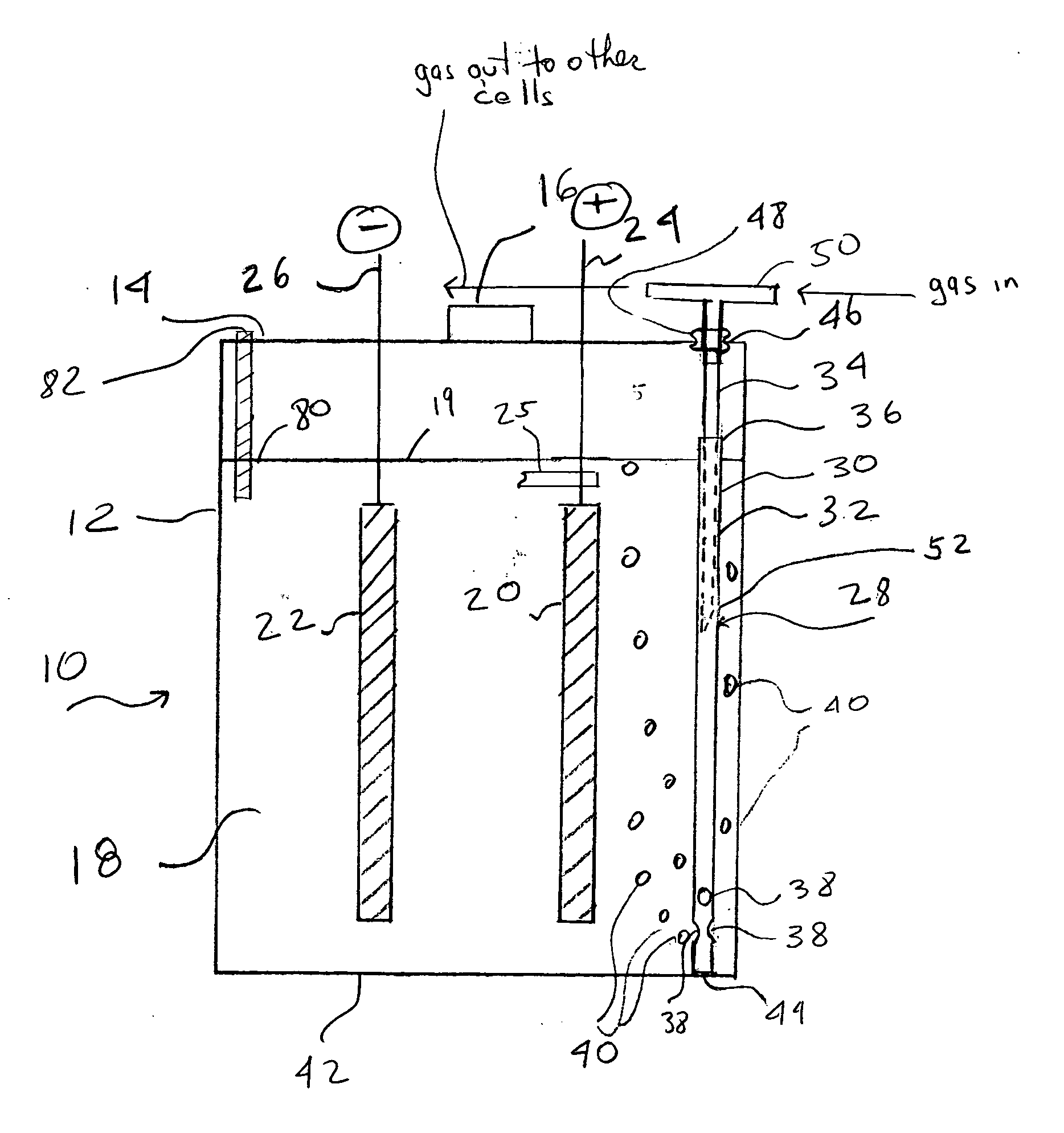
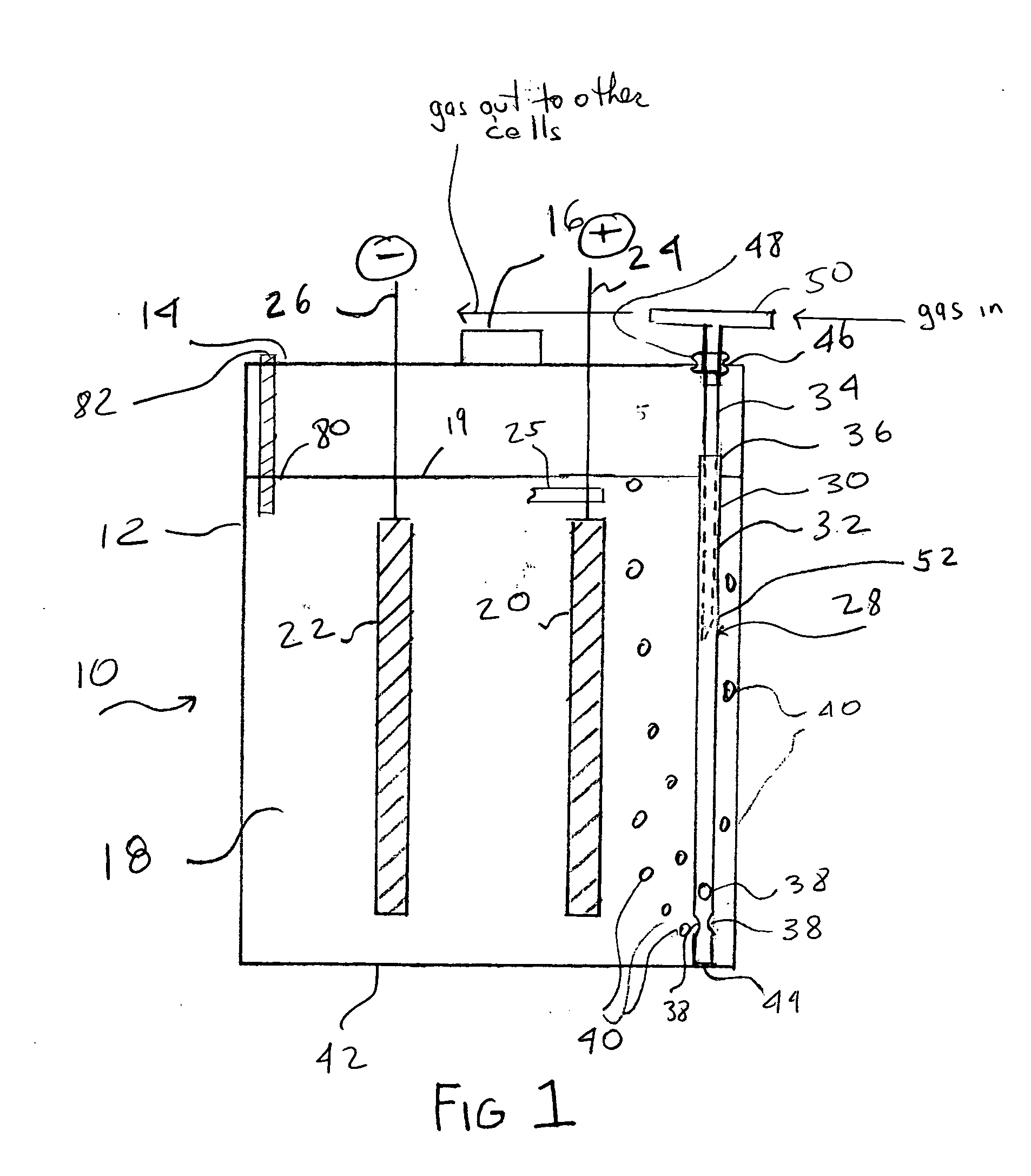
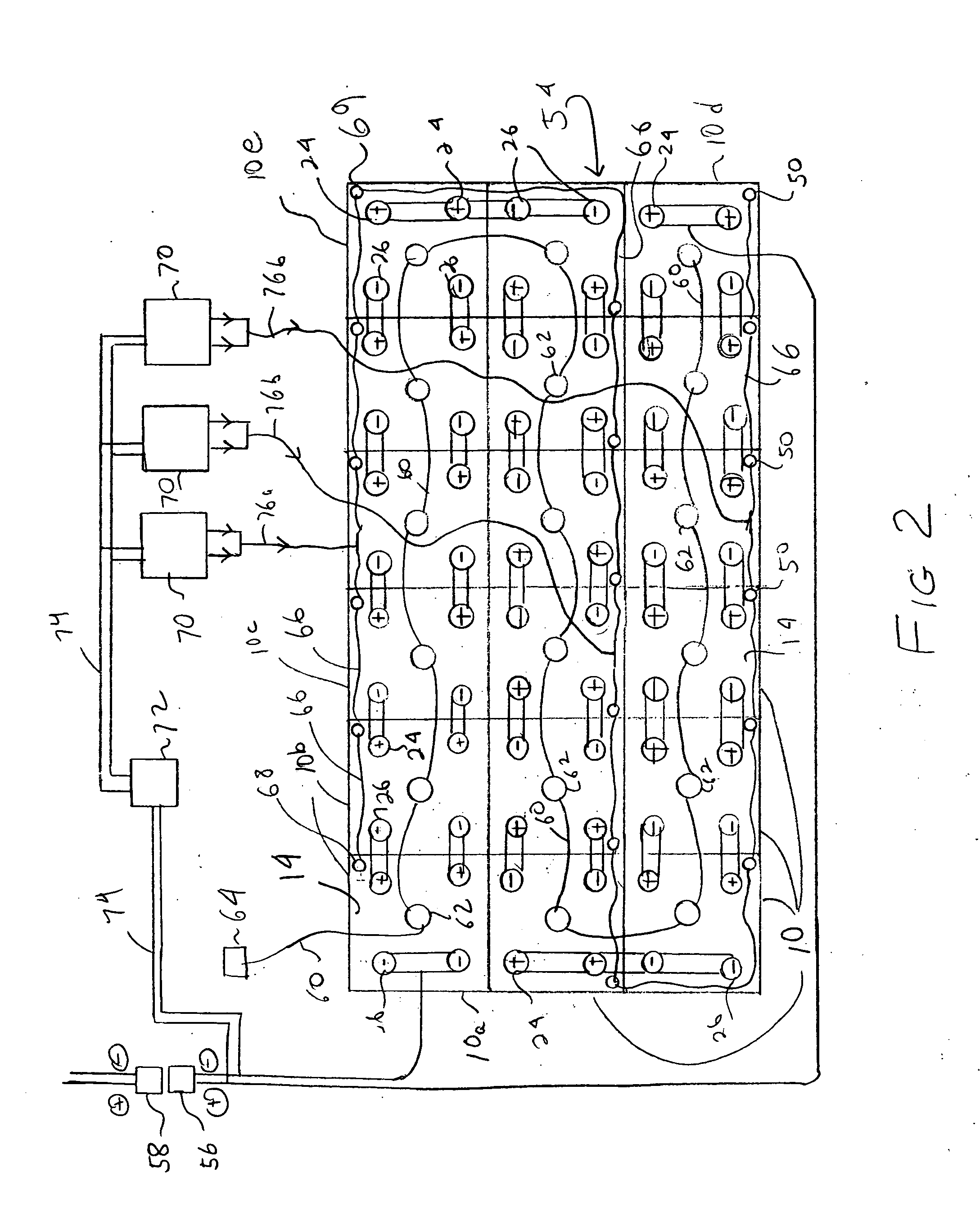
[0017] With reference to FIG. 1, a battery cell 10 is illustrated. The battery cell 10 is a single cell that typically is combined with multiple such cells 10 to form a battery. For example, lead acid batteries formed of 12, 18 and 24 such cells electrically connected in series are typical. The cell 10 has a housing 12, a housing cover 14 closing the top of the housing 12 and which has a vent 16 through which gasses from within the cell 10 can vent. An aqueous electrolyte 18 is provided in the housing, such as sulfuric acid for lead acid cells and sodium hydroxide for nickel alkaline cells. Immersed in the liquid electrolyte 18 is a positi...


PUM


Abstract

A method and device for cooling the electrolyte of aqueous battery cells such as lead acid batteries. The method includes the steps of delivering non-saturated gas to the electrolyte of in the battery cell, contacting said non-saturated gas with said electrolyte so that water from said electrolyte evaporates and thereby cools said electrolyte, and allowing the gas to escape from said battery cell, thereby removing heat from the electrolyte. An apparatus for carrying out the method is also provided. A fluid conduit is positioned to deliver the cooling air to the electrolyte within the cell. At least one pump delivers the air to the fluid conduit.

Description

CROSS REFERENCE TO RELATED APPLICATION [0001] This application claims the priority of U.S. Provisional Application No. 60 / 598,403 filed Aug. 2, 2004, which is hereby incorporated herein by reference.FIELD OF THE INVENTION [0002] The present invention is related to aqueous batteries, and more particularly to methods and devices for cooling the electrolyte of such batteries. BACKGROUND [0003] Aqueous batteries, such as industrial batteries that are typically made up of multiple battery cells connected in series, are used widely in industry in such uses as electric vehicles, e.g., fork lift trucks. As well known in the art, each cell contains positive and negative plates (electrodes) immersed in an electrolyte. Such batteries are used in service until depleted of charge, at which time the battery is removed and replaced with a freshly charged battery. The removed depleted battery is connected to a charger to be recharged. This method of operation requires several batteries for each veh...

Claims


Application Information

Patent Timeline
IPC IPC(8): H01M10/50H01M2/12
CPCH01M10/06H01M10/4235H01M10/443H01M10/486H01M10/5004Y02T10/7016H01M10/502H01M10/5042H01M10/5057H01M10/5067H01M10/5079H01M10/5016H01M10/625H01M10/63H01M10/6563H01M10/654H01M10/6556H01M10/6569H01M10/613Y02E60/10
Inventor JONES, WILLIAM E. M.
Owner JONES WILLIAM E M
Learn More