Laser processing apparatus

a technology of laser processing head and processing head, which is applied in the direction of welding apparatus, metal-working apparatus, manufacturing tools, etc., can solve the problems of difficult to increase the speed of the robot movement, no known publication can be found disclosing technology for simply solving the problem, and the cost of laser processing head is relatively high. , to achieve the effect of improving processing efficiency, shortening the cycle time, and facilitating the high speed movement of the laser processing head

Inactive Publication Date: 2006-02-23
FANUC LTD
View PDF5 Cites 10 Cited by
  • Summary
  • Abstract
  • Description
  • Claims
  • Application Information

AI Technical Summary

Benefits of technology

[0007] Accordingly, it is a basic object of the present invention to solve the above-mentioned problems in a laser processing apparatus. That is, it is an object of the present invention to provide a laser processing apparatus comprised of a robot having a processing tool mounted on the end of an arm thereof for laser processing, wherein high speed movement of a laser processing head is facilitated when no processing is being performed so as to shorten the cycle time and thereby improve the processing efficiency.
[0008] The present invention provides a processing head able to be moved by operation of additional axes of a robot on a processing tool so as to shorten the time of movement of the processing head at the time when no processing is being performed. More specifically, the present invention provides a laser processing apparatus including a robot having robot axes and at least one additional axis, a processing tool mounted on a forward end of an arm of the robot, and a controlling means for controlling the robot and the processing tool based on software processing, wherein the processing tool has a laser processing head able to be moved by the at least one additional axis, and the controlling means includes means for operating only the robot axes based on a program so as to control the movement of the laser processing head during processing and means for operating the at least one additional axis or both the at least one additional axis and the robot axes based on the program so as to control the movement of the laser processing head in a non-processing section.
[0009] This makes it easy to move the laser processing head at a high speed in the state where the robot axes are stopped to bring the robot arm to a rest (state where tool end point is at rest).
[0010] Here, the at least one additional axis may include an axis using a linear motor as a drive source for moving the laser processing head. In this case, the operation of the linear motor makes it easy to move the laser processing head at a high speed in a straight line while the robot arm is at rest.
[0011] Further, the laser processing apparatus may further include a means for changing robot control point definition data before execution of the next processing when operation of the at least one additional axis results in a change in the relative position of the laser processing head with respect to an end effector mounting surface of the forward end of the arm of the robot. In this case, when performing laser processing by executing a processing program defining a processing sequence, the change in the positional relationship between the control point (tool end point) of the robot and processing point (laser irradiation point) before and after movement of the processing head by the additional axes is compensated for, and deviation between a processing point designed by the processing program and the actual processing point is avoided.
[0012] According to the present invention, the ratio of the laser output time in the cycle time of the laser processing can be longer to improve the processing efficiency of the laser processing system. Further, this can contribute to reduction of the cost of products.

Problems solved by technology

However, laser processing apparatuses are relatively expensive compared with spot welding machines etc., and therefore, for them to take the place of other conventional processing apparatuses, it is desirable to improve the processing efficiency by shortening the cycle time.
However, in general, movement of a robot by a robot axial operation is accompanied with movement of an arm having a large inertia.
Therefore, it is difficult to increase the speed of the robot movement.
However, no known publication can be found disclosing technology for simply solving the problem derived from the fact that the speed of movement of the laser processing head ends up being determined by the speed of movement of the robot.

Method used


Image

  • Laser processing apparatus
  • Laser processing apparatus
  • Laser processing apparatus

Examples


Embodiment Construction

[0016] Embodiments of the present invention will be described below with reference to the drawings.

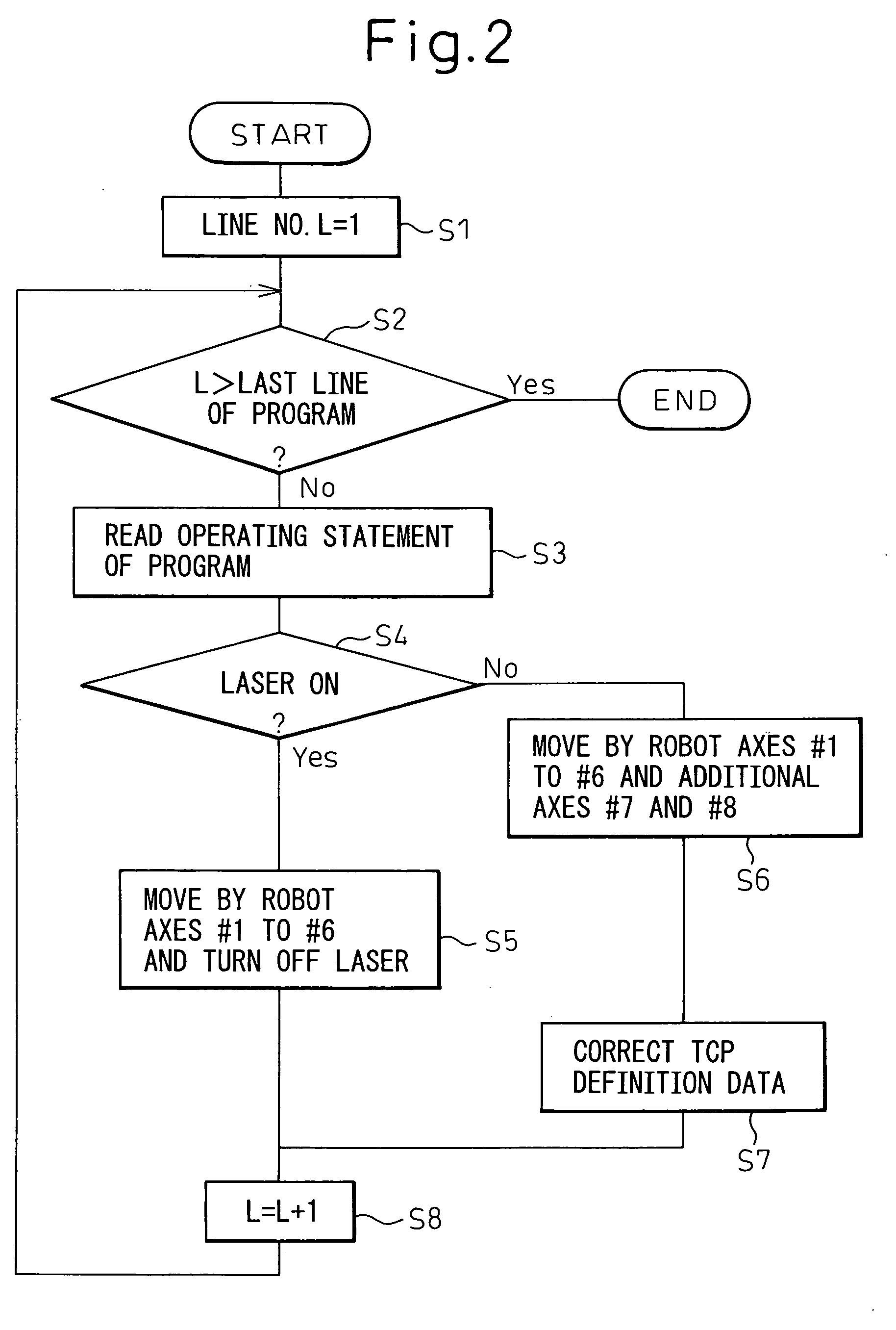
[0017] In the following explanation, the term “#n” should be understood as indicating the n-th axis of the robot controlled by the robot control device through the servo controllers for the different axes.

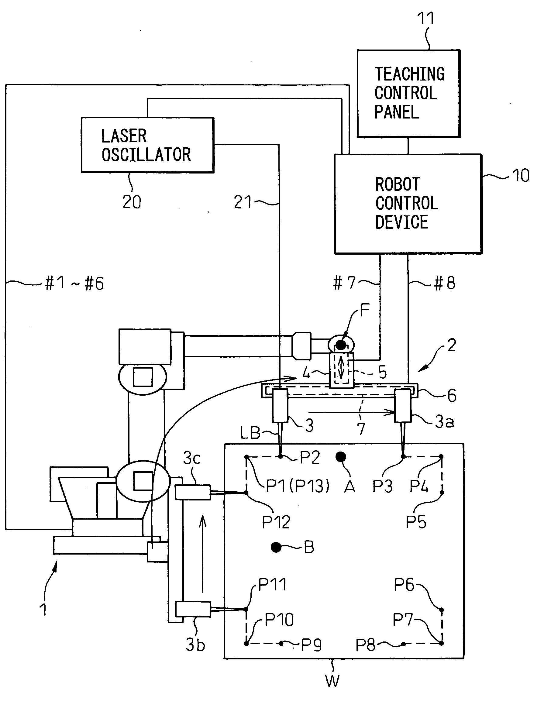
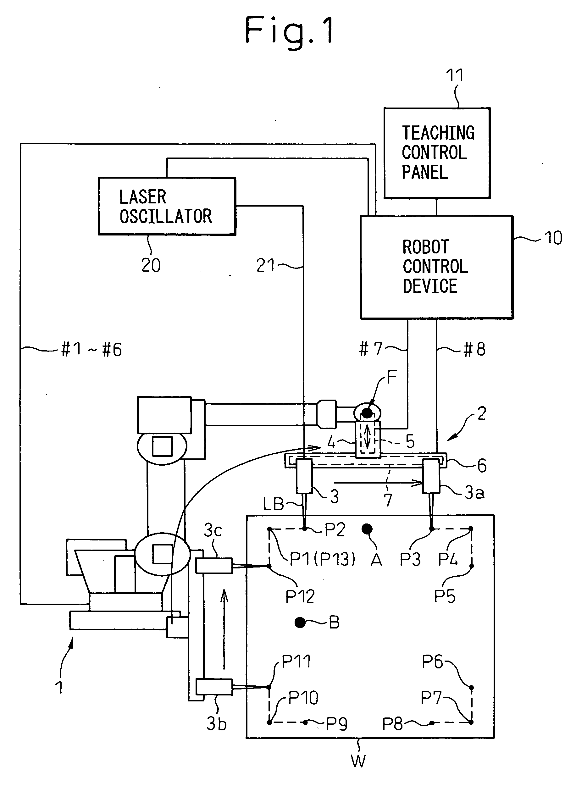
[0018]FIG. 1 is a view showing the principal configuration of a laser processing apparatus according to an embodiment of the present invention. Referring to FIG. 1, a robot control device 10 functions as the means for controlling the system as a whole and is provided with a central processing unit (main CPU, hereinafter referred to simply as “CPU”). The CPU is connected through buses to a memory comprised of a RAM and ROM, a teaching control panel interface connected to a teaching control panel 11, a laser apparatus input / output interface connected to a laser oscillator 20, a servo controller for controlling the servo motors for driving the axes #1 to #6 of the robot 1, and a servo ...


PUM

PropertyMeasurementUnit
speedaaaaaaaaaa
inertiaaaaaaaaaaa
cycle timeaaaaaaaaaa

Abstract

A laser processing apparatus includes a six-axis robot operating by robot axes controlled by a robot control device and a processing tool mounted on the end of the arm of the robot. A processing head is provided on a horizontal movement mechanism provided on a horizontal movement mechanism support base, which is in turn supported by a carrier able to move on a vertical movement mechanism. The vertical movement mechanism and the horizontal movement mechanism are driven by additional axes controlled by the robot control device. In a non-processing section of the workpiece etc., only the additional axes are operated to move the processing head at a high speed and shorten the cycle time. When operating the additional axes to move, the data of the relative position of the control point (tool end point) with respect to a fixed point on the arm forward end is corrected each time.

Description

BACKGROUND OF THE INVENTION [0001] 1. Field of the Invention [0002] The present invention relates to a laser processing apparatus, and more particularly to a laser processing apparatus having a processing tool mounted at the forward end of an arm of a robot for laser processing. [0003] 2. Description of the Related Art [0004] In recent years, technology mounting a processing tool comprised of a laser processing head (hereinafter simply also referred to as a “processing head”) on the end of an arm of a robot for laser processing has been growing in fields of application. It draws attention, for example, as processing technology for taking the place of spot welding technology etc., in mainly the automotive industry. However, laser processing apparatuses are relatively expensive compared with spot welding machines etc., and therefore, for them to take the place of other conventional processing apparatuses, it is desirable to improve the processing efficiency by shortening the cycle tim...

Claims


Application Information

Patent Timeline
Patent Type & Authority Applications(United States)
IPC IPC(8): B23K26/08
CPCB23K26/0884
Inventor OTSUKA, KAZUHISAFURUYA, YOSHITAKE
Owner FANUC LTD
Why Eureka
Try Eureka