System for setting the span load distribution of a wing

a technology of span load and distribution system, which is applied in the direction of automatic actuation, navigation instruments, instruments, etc., can solve the problems of not being able to adapt and requiring a considerable system effort, so as to reduce the induced resistance, reduce the local load, and reduce the effect of airflow separation

Active Publication Date: 2006-02-23
AIRBUS OPERATIONS GMBH
View PDF13 Cites 52 Cited by
  • Summary
  • Abstract
  • Description
  • Claims
  • Application Information

AI Technical Summary

Benefits of technology

[0013] The optimisation potential in relation to the start lift/drag ratio is primarily provided by way of the induced resistance. By adjusting the excursion of the flap elements, the induced resistance can be reduced. The outboard flap element may be positioned at a larger angle than the inboard flap element. In this way the load distribution of the wing is displaced towards the outside; as a result of this displacement, lift distribution can be approximated more closely to an “ideal elliptic” distribution.
[0014] The optimisation potential in relation to maximum lift is provided by the option of taking some of the load off the wing in the region where airflow separation occurs and limits maximum lift. By a targeted reduction of the flap excursion i

Problems solved by technology

Such a high-lift system is believed to not make it possible to adapt in any way the span load distribution to increase the start lift/drag ratio and the maximum lift.
Another already-known high-lift system (Dargel G., et al, “Entwicklung eines Flügels mit multifunktionalen Steuerflächen” [Development of a wing with multifunctio

Method used


Image

  • System for setting the span load distribution of a wing
  • System for setting the span load distribution of a wing

Examples


Embodiment Construction

[0020] Below, identical or corresponding components have the same reference characters in the figures.

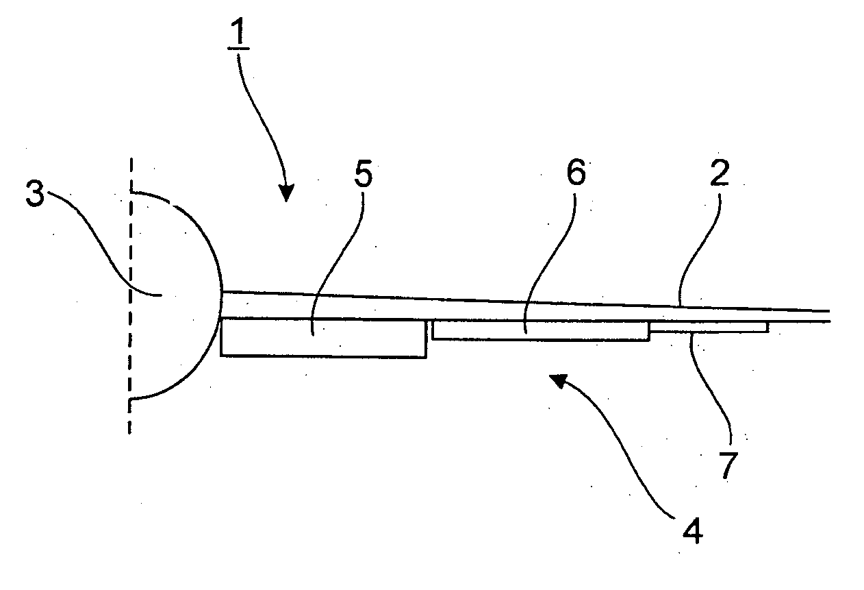
[0021]FIG. 1 shows a system 1 for setting a span load distribution of a wing 2. FIG. 1 shows the right-hand wing 2 of an aircraft (not shown), which wing extends outwards from the fuselage 3.

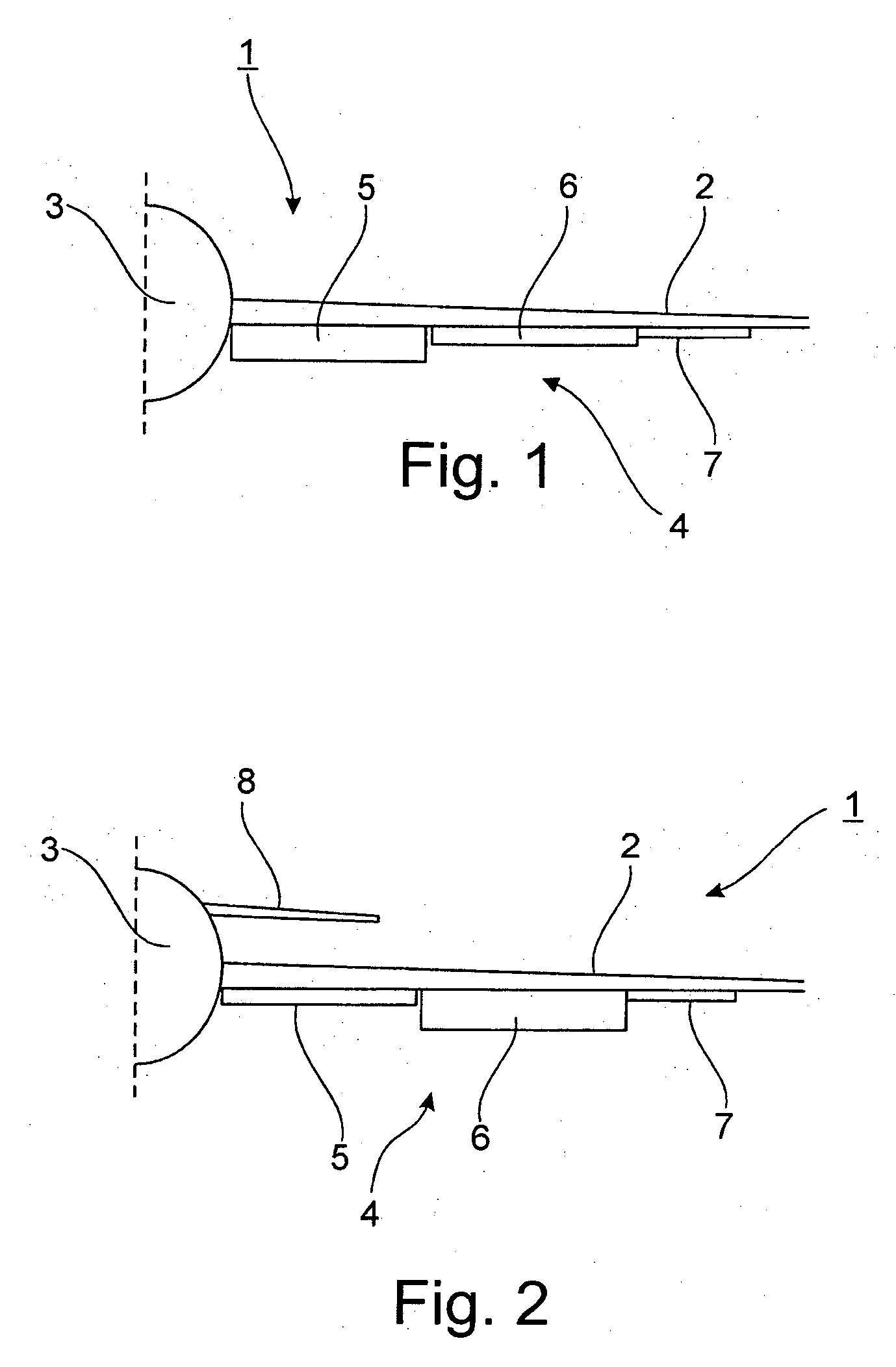
[0022] The wing 2 comprises a conventional base flap system 4. The conventional base flap system 4 comprises an inboard landing flap 5, an outboard landing flap 6 and an aileron 7.

[0023] According to an exemplary embodiment, the inboard landing flap 5 and the outboard landing flap 6 can be positioned independently of each other. To this effect a drive system (not shown) can be used which is able to position the inboard landing flap 5 and the outboard landing flap 6 independently of each other.

[0024] According to an exemplary embodiment of the invention, for example the inboard landing flap 5 of the wing 2 is mechanically coupled with an inboard landing flap of the other wing (not shown). Lik...


PUM


Abstract

A system for setting a span load distribution of a wing of an aircraft with a base flap system comprises at least one inboard flap element and one outboard flap element, which elements in the direction of the span are arranged on the trailing edge of the wing, and can be positioned relative to the span direction of the wing. The flap elements are not mechanically coupled with each other and are controlled independently of each other for the purpose of setting the span load distribution.

Description

CROSS-REFERENCE TO RELATED APPLICATIONS [0001] This application claims the benefit of the filing date of U.S. Provisional Patent Application No. 60 / 603,110 filed Aug. 19, 2004, the disclosure of which is hereby incorporated herein by reference.BACKGROUND OF THE INVENTION [0002] The present invention relates to a system for setting the span load distribution of a wing, in particular high-lift systems on the wings of large commercial aircraft. [0003] Almost without exception, in already-known systems (Rudolph P. K. C., High-Lift Systems on Commercial Subsonic Airliners, NASA CR 4746) the trailing edge of wings of large commercial aircraft has landing flap elements that are divided in the direction of the span. The reasons for this are the geometry of the wing, the dimensions of the components, and the control of the flap elements by the system. In a conventional design of the high-lift system, the landing flap elements are coupled to each other, i.e. they are extended at the same angl...

Claims


Application Information

Patent Timeline
IPC IPC(8): B64C3/00
CPCB64C3/10B64C3/50B64C9/12Y02T50/145B64C13/16B64C13/24Y02T50/12B64C9/18Y02T50/10
Inventor RECKZEH, DANIEL
Owner AIRBUS OPERATIONS GMBH
Why Eureka
Try Eureka