Servo motor driving apparatus and servo motor driving method

a servo motor and driving apparatus technology, applied in the direction of electric controllers, instruments, ignition automatic control, etc., can solve the problems of low inability to reuse regenerative energy, and large converter circuit block size, so as to improve the regenerative energy reuse efficiency of servo motors

Inactive Publication Date: 2006-02-23
FANUC LTD
View PDF5 Cites 12 Cited by
  • Summary
  • Abstract
  • Description
  • Claims
  • Application Information

AI Technical Summary

Benefits of technology

[0017] In view of the above problems, it is an object of the present invention to provide a servo motor driving apparatus and a servo motor driving method for driving a plurality of servo motors, wherein provisions are made to improve the reuse efficiency of servo motor regenerative energy.

Problems solved by technology

As a result, an energy loss occurs in the power devices and the power supply lines in the converter circuit 3, resulting in the problem that the reuse efficiency of the regenerative energy is low.
Furthermore, as most of the electric power required to drive the servo motor 5 is derived from the power supply via the converter circuit, there has been the problem in that the size of the converter circuit block increases.
There has therefore been the problem that not only is it impossible to reuse the regenerative energy, but because of the need to prevent thermal breakdown of the regenerative resistor R due to excessive current flow, the voltage between the output terminals of the converter circuit during regeneration can be increased only a little, which imposes a design constraint.
Therefore, the reuse of the regenerative energy has been greatly limited in practice.

Method used


Image

  • Servo motor driving apparatus and servo motor driving method
  • Servo motor driving apparatus and servo motor driving method
  • Servo motor driving apparatus and servo motor driving method

Examples


Embodiment Construction

[0038] Preferred embodiments of the present invention will be described in detail below with reference to the accompanying drawings. FIG. 4 is a diagram schematically showing the configuration of an inverter apparatus which constitutes a servo motor driving apparatus according to an embodiment of the present invention.

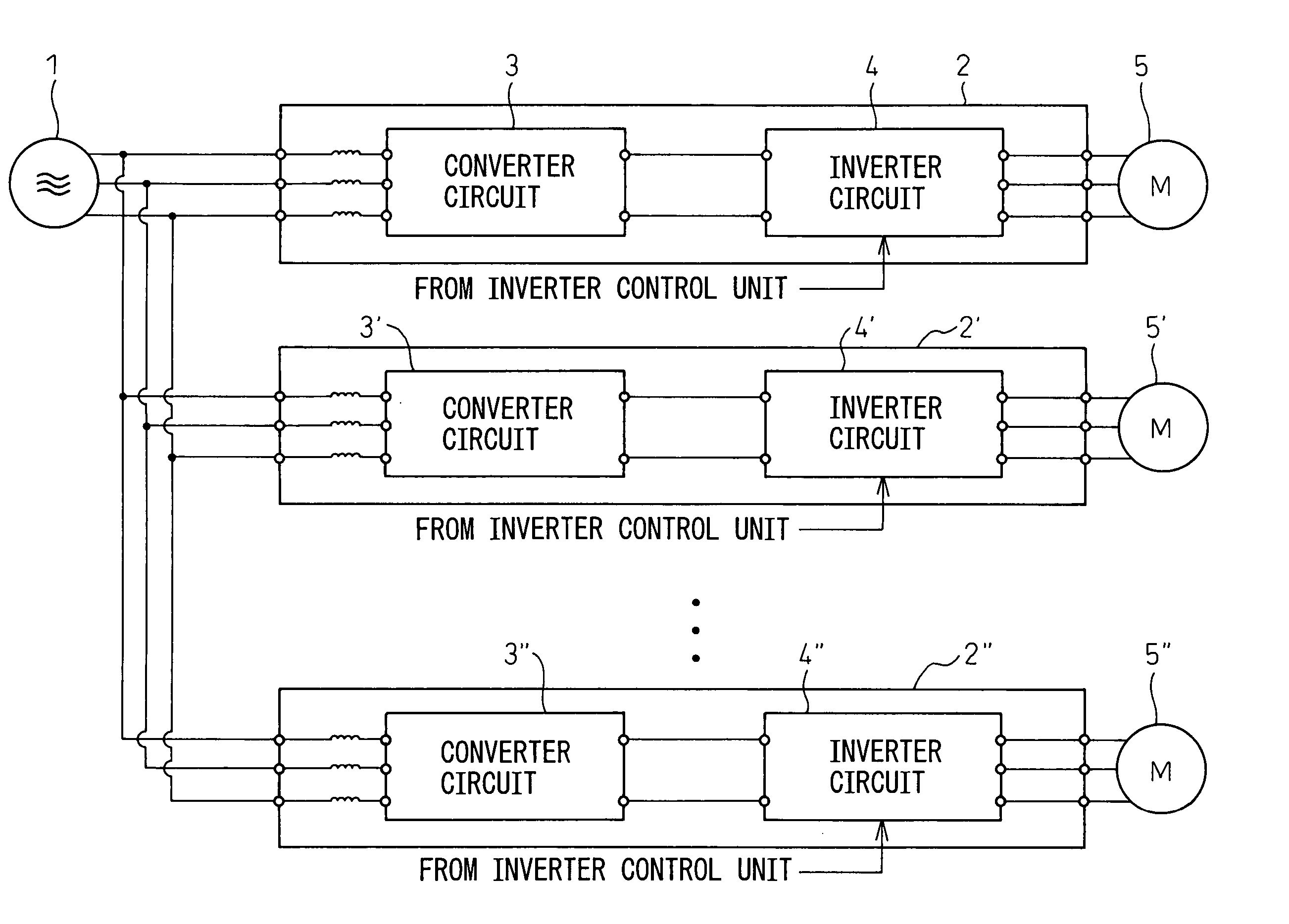
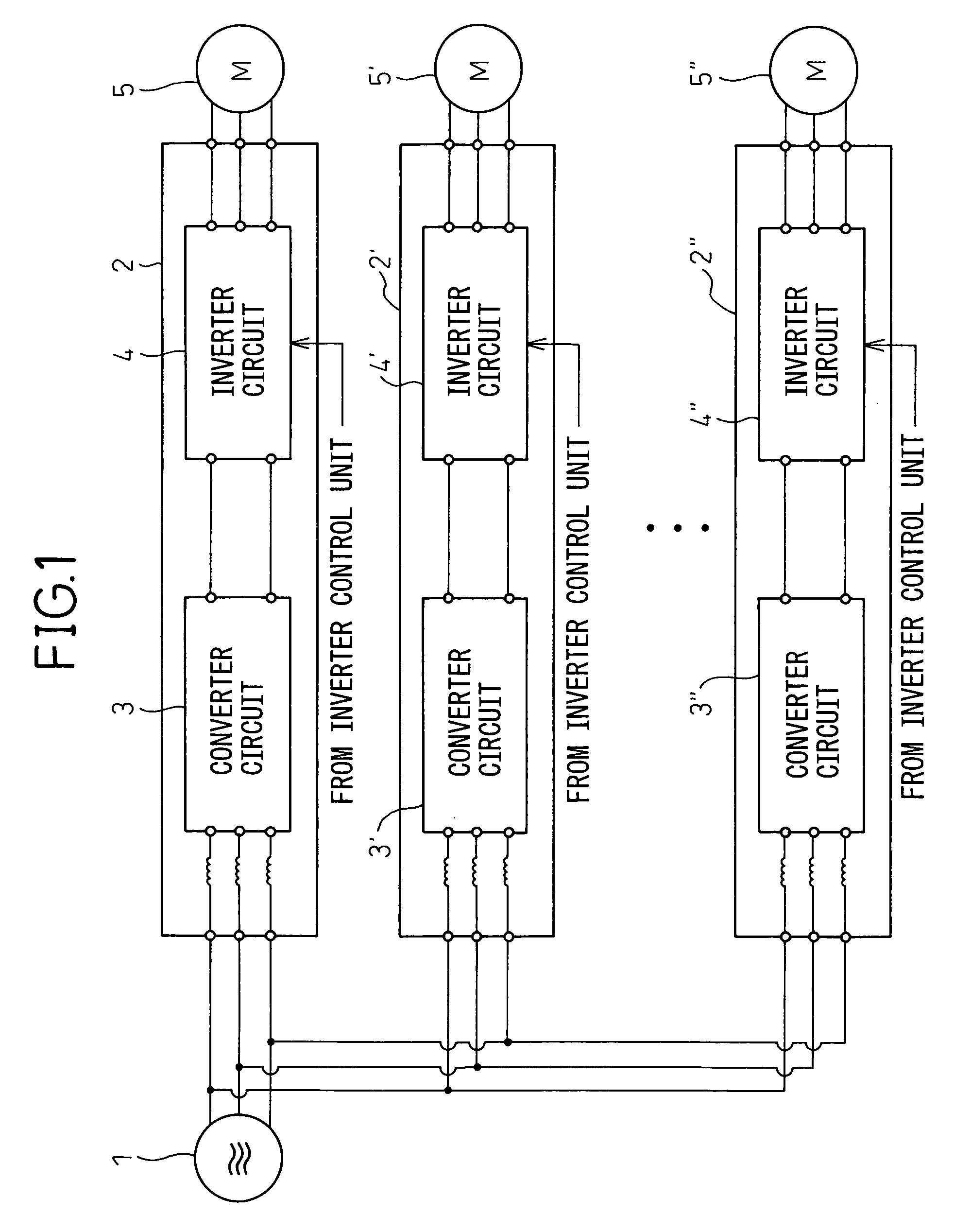
[0039] As shown, the inverter apparatus 2 comprises one converter circuit 3 and a plurality of inverter circuits 4, 4′, . . . , 4″ to which common DC power is supplied from the converter circuit 3. The converter circuit 3 converts AC power, supplied from a three-phase AC power supply 1 via reactance 8, into DC power and outputs the DC power at its output terminals O1 and O2.

[0040] Input terminals I1, I1′, . . . , I1″, each being one input terminal of each of the inverter circuits 4, 4′, . . . , 4″, are connected in common to the output terminal O1, while the other input terminals I2, I2′, . . . , I2″ are connected in common to the output terminal O2. In this configur...


PUM


Abstract

An object of the present invention is to provide a servo motor driving apparatus and a servo motor driving method for driving a plurality of servo motors, wherein provisions are made to improve the reuse efficiency of servo motor regenerative energy. The servo motor driving apparatus (2) comprises: a plurality of inverter circuits (4, 4″, 4″) which supply AC power to the plurality of servo motors (5, 5′, 5″), respectively; a converter circuit (3) which supplies electric power in common to the inverter circuits (4, 4′, 4″); and an inverter control unit (6) which, when giving an acceleration command to any one of the servo motors, gives a deceleration command to another one of the servo motors at the same time.

Description

BACKGROUND OF THE INVENTION [0001] 1. Field of the Invention [0002] The present invention relates to a servo motor driving apparatus and method in which AC power is converted by a converter circuit into DC power and the DC power is further converted by an inverter circuit into AC power and is supplied to a servo motor to drive the servo motor. More particularly, the invention relates to a servo motor driving apparatus and method for driving a plurality of servo motors, coupled to a moving mechanism, to supply motive power to the moving mechanism. [0003] 2. Description of the Related Art [0004]FIG. 1 is a diagram for explaining a prior art apparatus for driving a plurality of servo motors. The plurality of servo motors 5, 5′, . . . , 5″ are connected to inverter apparatuses 2, 2′, . . . , 2″, respectively, which derive electric power from a three-phase AC power supply 1. [0005] In the inverter apparatuses 2, 2′, . . . , 2″, the AC power supplied from the three-phase AC power supply 1...

Claims


Application Information

Patent Timeline
Patent Type & Authority Applications(United States)
IPC IPC(8): H02P7/06H02P5/00
CPCH02P5/74
Inventor OKAMOTO, TAKASHIYAMAGUCHI, AKIRAHANYU, SHIGEKIYAMADA, YUUICHI
Owner FANUC LTD
Why Eureka
Try Eureka