Polarizing beam splitter device, interferometer module, lithographic apparatus, and device manufacturing method

a polarizing beam and splitter technology, applied in the direction of measurement devices, instruments, optics, etc., can solve the problems of requiring high accuracy and stability, affecting the accuracy of polarizing beam splitter devices, etc., to achieve the effect of precise and more stable positioning of its component parts and efficient us

Inactive Publication Date: 2006-02-23
ASML NETHERLANDS BV
View PDF9 Cites 23 Cited by
  • Summary
  • Abstract
  • Description
  • Claims
  • Application Information

AI Technical Summary

Benefits of technology

[0012] Embodiments of the invention include an optical element which is configured to retroreflect radiation, i.e. a retroreflector, and which is given a design in which a more efficient use is made of the material of the retroreflector, and which allows for a more precise and more stable positioning of its component parts, both mutual positioning and with respect to other parts of e.g. an interferometer system.

Problems solved by technology

If retroreflectors do not have such a handler portion, functional surfaces, such as the retroreflector surface, may be damaged during operation.
After mounting, the handler portion is useless, which is a waste of material.
Furthermore, the mounting of a retroreflector in e.g. an interferometry system with a beam splitter etc. is highly critical, and requires a high accuracy and stability in time.
The various known ways of mounting a retroreflector are not always satisfactory in this respect.

Method used


Image

  • Polarizing beam splitter device, interferometer module, lithographic apparatus, and device manufacturing method
  • Polarizing beam splitter device, interferometer module, lithographic apparatus, and device manufacturing method
  • Polarizing beam splitter device, interferometer module, lithographic apparatus, and device manufacturing method

Examples


Embodiment Construction

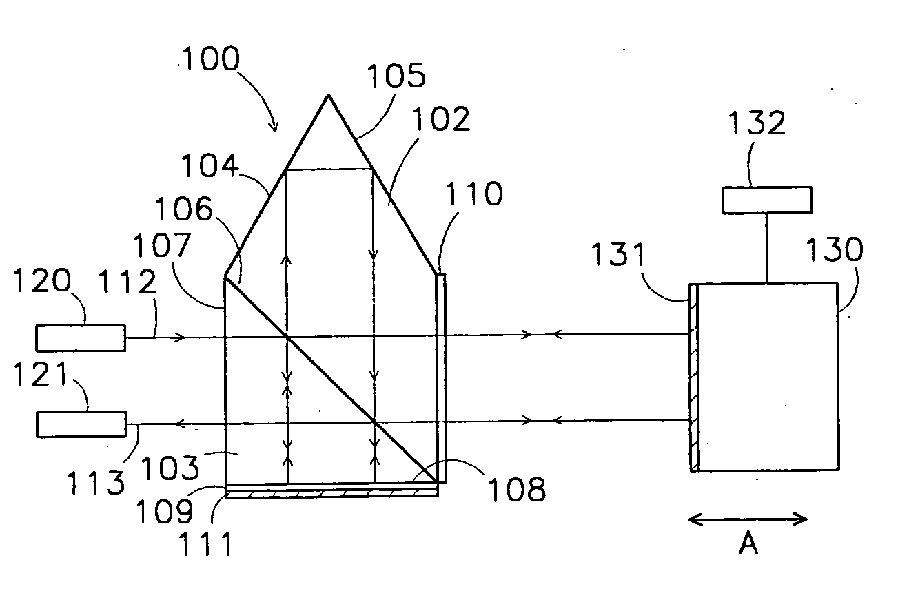
[0038] A polarizing optical beam splitter device is a device that is able to split a non-polarized beam of radiation into two separate beams of different polarization. One of the beams is transmitted, while the other beam is reflected. A polarizing beam splitter device generally includes at least one transparent optical body, onto which a polarizing beam splitter layer is provided.

[0039] A retroreflector surface of an optical element is a surface, that may be a complex surface, which has the property of retroreflecting a beam of radiation that is incident on that surface, at least for a certain non zero solid angle. In practice, this almost always relates to three mutually perpendicular planar faces, i.e. a corner of a mathematical cube.

[0040] A retroreflector portion, of an optical element, includes a volume of optically transparent material that is bounded by at least a retroreflector surface and an imaginary surface to form a continuous outer surface of the retroreflector porti...


PUM


Abstract

The invention relates to a polarizing beam splitter device, an interferometer module system, a lithographic apparatus, and a device manufacturing method. The polarizing beam splitter device includes an optical element and a polarizing beam splitter layer. The optical element includes a retroreflector surface having three mutually perpendicular faces of high optical quality, a radiation beam passage surface and a handling surface. By designing the optical element, in particular the handling portion, to the shape of a beam splitter element, such as a prism, the handling portion, and thus the polarizing optical beam splitter device etc. itself, may be made more compact and with fewer surfaces to be polished and/or antireflection-coated. The positioning of the parts in a beam splitter is more reliable. Devices, systems in which the polarizing beam splitter device has been incorporated, such as a polarizing beam splitter device with quarter wave plates and a reference mirror fixed thereto, may also be made more compact, accurate and reliable.

Description

BACKGROUND [0001] 1. Field of the Invention [0002] The present invention relates to lithographic apparatus and methods. [0003] 2. Description of the Related Art [0004] A lithographic apparatus is a machine that applies a desired pattern onto a substrate, usually onto a target portion of the substrate. A lithographic apparatus can be used, for example, in the manufacture of integrated circuits (ICs). In that instance, a patterning device, which is alternatively referred to as a mask or a reticle, may be used to generate a circuit pattern to be formed on an individual layer of the IC. This pattern can be transferred onto a target portion (e.g. including part of, one, or several dies) on a substrate (e.g. a silicon wafer). Transfer of the pattern is typically via imaging onto a layer of radiation-sensitive material (resist) provided on the substrate. In general, a single substrate will contain a network of adjacent target portions that are successively patterned. Known lithographic app...

Claims


Application Information

Patent Timeline
Patent Type & Authority Applications(United States)
IPC IPC(8): G01B9/02
CPCG01B9/02G03F7/70775G02B27/283G02B5/122G01B9/02051G01B2290/15G01B2290/70
Inventor VAN DER PASCH, ENGELBERTUS ANTONIUS FRANSISCUS
Owner ASML NETHERLANDS BV
Why Eureka
Try Eureka