Generalized m-rank beamformers for mimo systems using successive quantization

Active Publication Date: 2006-02-23
SISVEL INT
View PDF10 Cites 64 Cited by
  • Summary
  • Abstract
  • Description
  • Claims
  • Application Information

AI Technical Summary

Benefits of technology

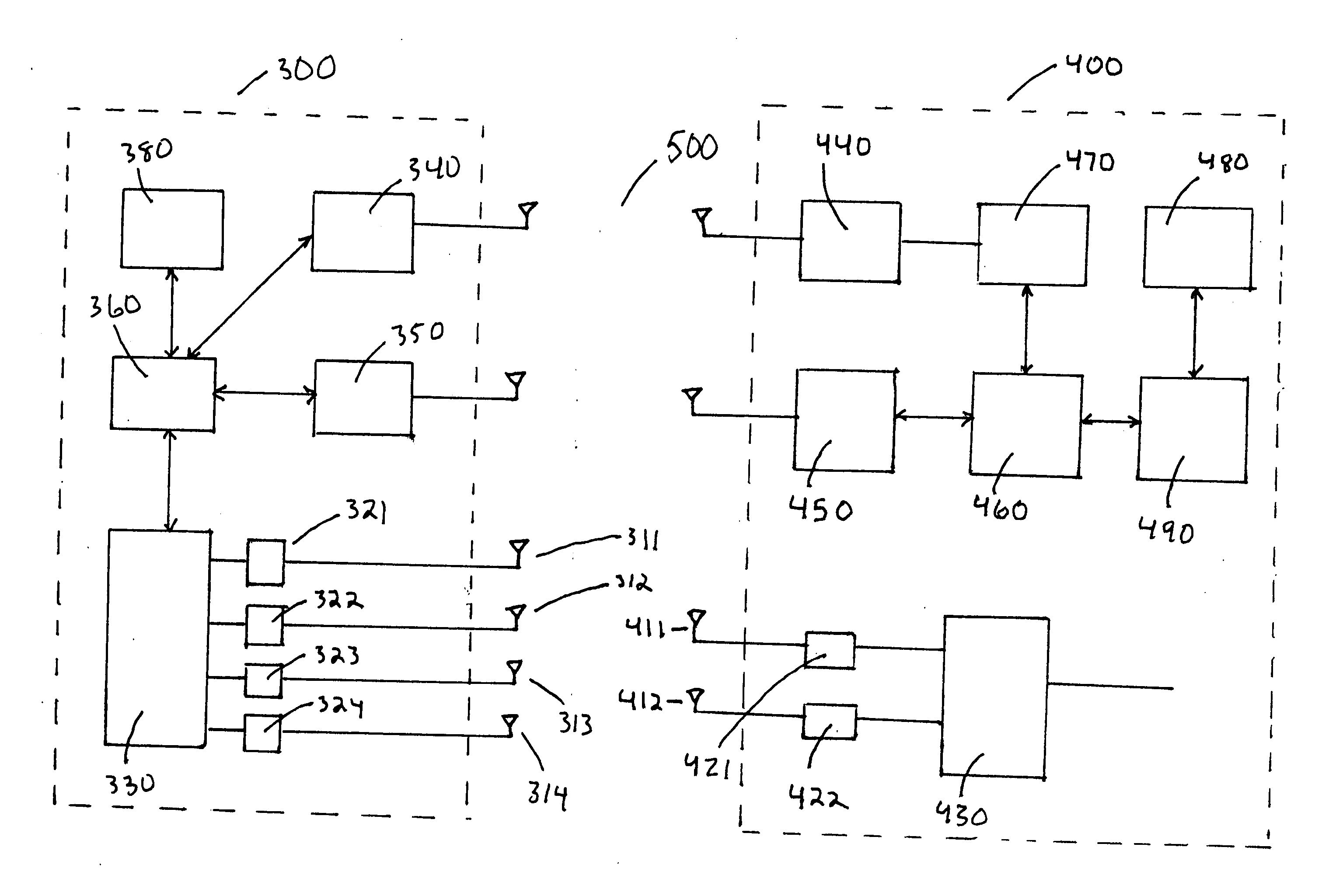
[0021] A further alternate embodiment of the present invention comprises a mobile station having a test signal receiver for receiving a test signal generated by a base station; a channel matrix calculator for calculating the eigenvectors of the channel matrix determined by observing the effect of the channel on the test signal; a beamforming codebook comprised of codebook vectors identical to those in the beamforming codebook of the base station; a beamforming vector selector for selecting which

Problems solved by technology

Complexity and implementation issues, as well as performan

Method used


Image

  • Generalized m-rank beamformers for mimo systems using successive quantization
  • Generalized m-rank beamformers for mimo systems using successive quantization
  • Generalized m-rank beamformers for mimo systems using successive quantization

Examples


Embodiment Construction

I. Preferred Beamforming Methods in Accordance with the Present Invention

[0026] The beamforming methods presented herein result in improved performance at provably lower computational complexity compared to the space time coding schemes currently proposed for multiple antenna systems. Low receiver complexity is an important design goal for downlink transmission where the handset (receiver) is constrained in its computational abilities.

[0027] It is well-known that channel state information at the transmitter can enhance system performance significantly. However, in practical systems, only partial channel information is available at the transmitter due to the limited nature of feedback resources. Hence, it is important to design feedback-based transmission schemes for situations where partial channel information is available at the transmitter. Transmission schemes for single receive antenna systems utilizing quantized channel information have been developed.

[0028] Presented herein ...


PUM


Abstract

The telecommunications system described herein implements a multi-rank beamformer for use in wireless systems equipped with multiple transmit and multiple receive antennas. The multi-rank beamformer uses finite-rate feedback of channel conditions to achieves close to theoretical performance indicated by the water-filling algorithm, while avoiding the computational complexity associated with space time codes. In addition, the multi-rank beamforming system described herein improves on the performance of unit rank beamforming methods by maintaining the gains over space time codes over a broader range of transmission rates.

Description

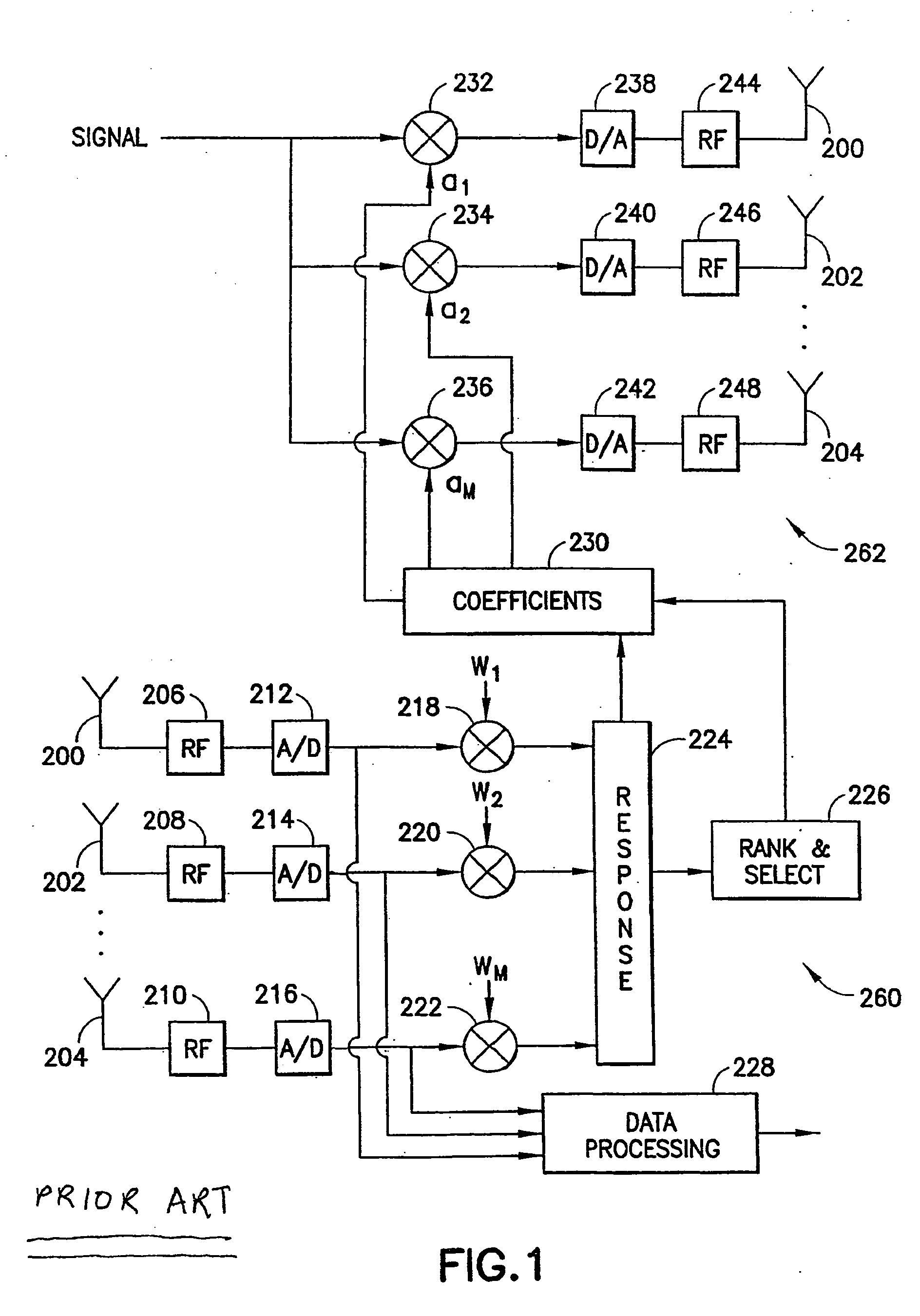
TECHNICAL FIELD [0001] The field of the invention generally concerns beamformers for use in wireless systems equipped with multiple transmit and multiple receive antennas, and more particularly concerns higher-rank beamforming methods where finite-rate feedback information concerning the channel state is available at the transmitter. BACKGROUND OF THE INVENTION [0002] Various beamforming methods for wireless systems equipped with multiple transmit and multiple receive antennas are known in the art. At present, space time coding schemes are currently proposed for multiple antenna systems. [0003]FIG. 1, taken from U.S. Pat. No. 6,584,302, assigned to the assignee hereof, presents a transceiver that has a group of antenna elements 200-204 for transmitting and receiving. The transceiver is usually a base station but it can also be subscriber equipment. The antenna with several elements can be an antenna array or some other kind of cluster of antenna elements. Referring to receiver 260, ...

Claims


Application Information

Patent Timeline
IPC IPC(8): H04B7/02H04L1/02
CPCH04B7/0417H04B7/043H04B7/0663H04B7/0634H04B7/0639H04B7/0443
Inventor MUKKAVILLI, KRISHNA KIRANSABHARWAL, ASHUTOSHAAZHANG, BEHNAAM
Owner SISVEL INT
Why Eureka
Try Eureka