Developing apparatus and method

a technology of developing apparatus and development method, which is applied in the direction of photomechanical apparatus, instruments, coatings, etc., can solve the problems of not considered to be much of a problem, and deteriorating the accuracy in realizing a precise line width, etc., and achieves high in-surface uniformity

Inactive Publication Date: 2006-02-23
TOKYO ELECTRON LTD
View PDF9 Cites 23 Cited by
  • Summary
  • Abstract
  • Description
  • Claims
  • Application Information

AI Technical Summary

Benefits of technology

[0007] It is, therefore, an object of the present invention to provide a developing apparatus and method, whereby when a substrate whose surface has a resist coated thereon and is exposed to light is rotated and provided with the developer, a developer flow can be controlled on the substrate and a pattern having a high in-surface uniformity can be formed.
[0018] In accordance with the present invention, after the developer is supplied in a spiral shape while the wafer W is rotated forwardly, the wafer W is then rotated backwardly. Accordingly, a flow pattern of the developer is changed on the wafer W, so that the developer can uniformly reach all over the fine pattern in comparison with one-way flow of the developer. As a result, the developer can reach all fine parts of the pattern, thereby producing a pattern of a highly uniform line width after a developing process.

Problems solved by technology

However, the aforementioned developing method has following drawbacks.
Accordingly, the developer may not uniformly reach all over the pattern, especially over a downstream side portion of the pattern, thereby deteriorating the accuracy in realizing a precise line width.
But, since a nonsmooth solution flow causes only a very slight deterioration in the accuracy in realizing a precise line width and, thus, it was not conventionally considered to be much a problem.

Method used


Image

  • Developing apparatus and method
  • Developing apparatus and method
  • Developing apparatus and method

Examples


Embodiment Construction

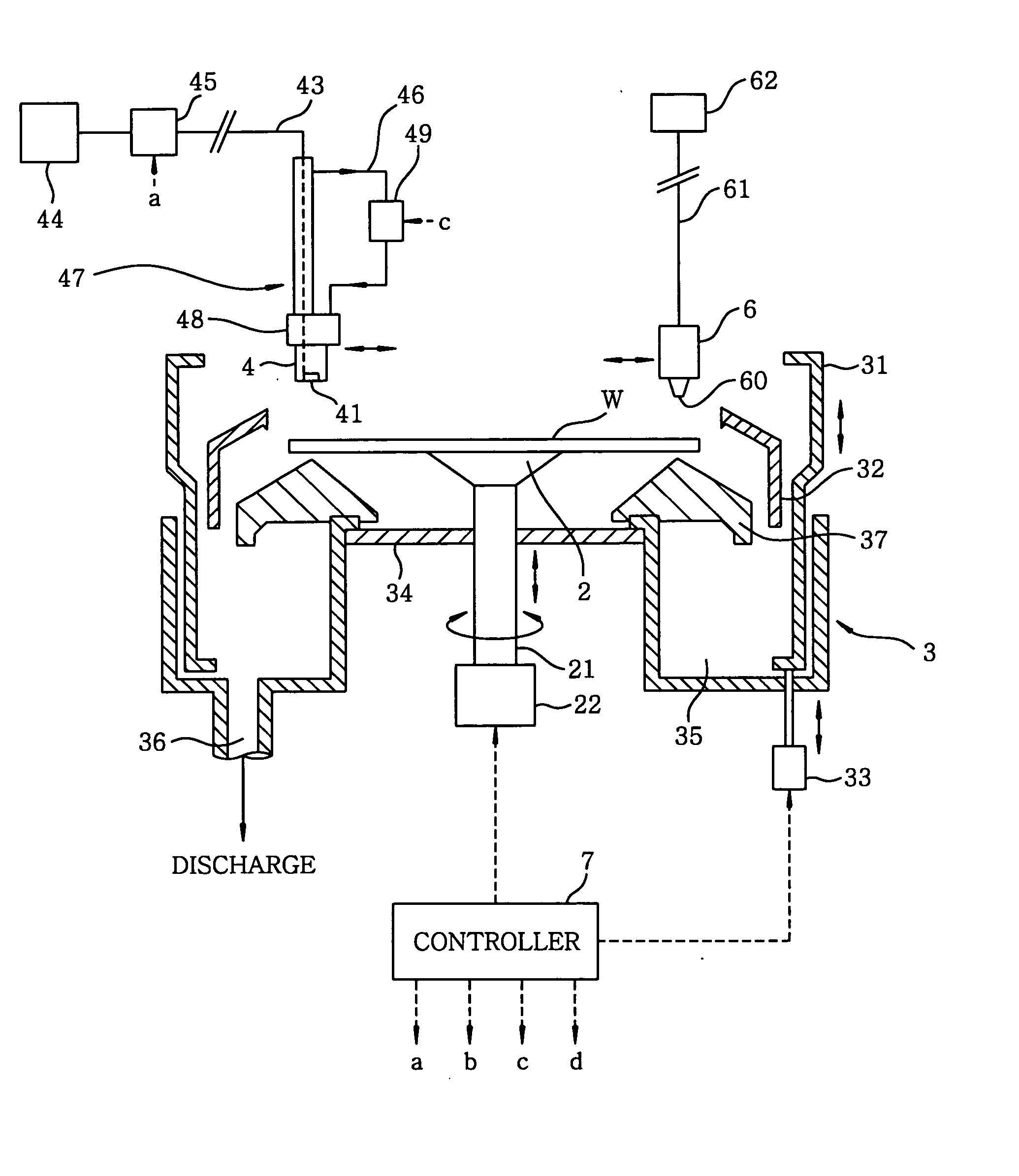
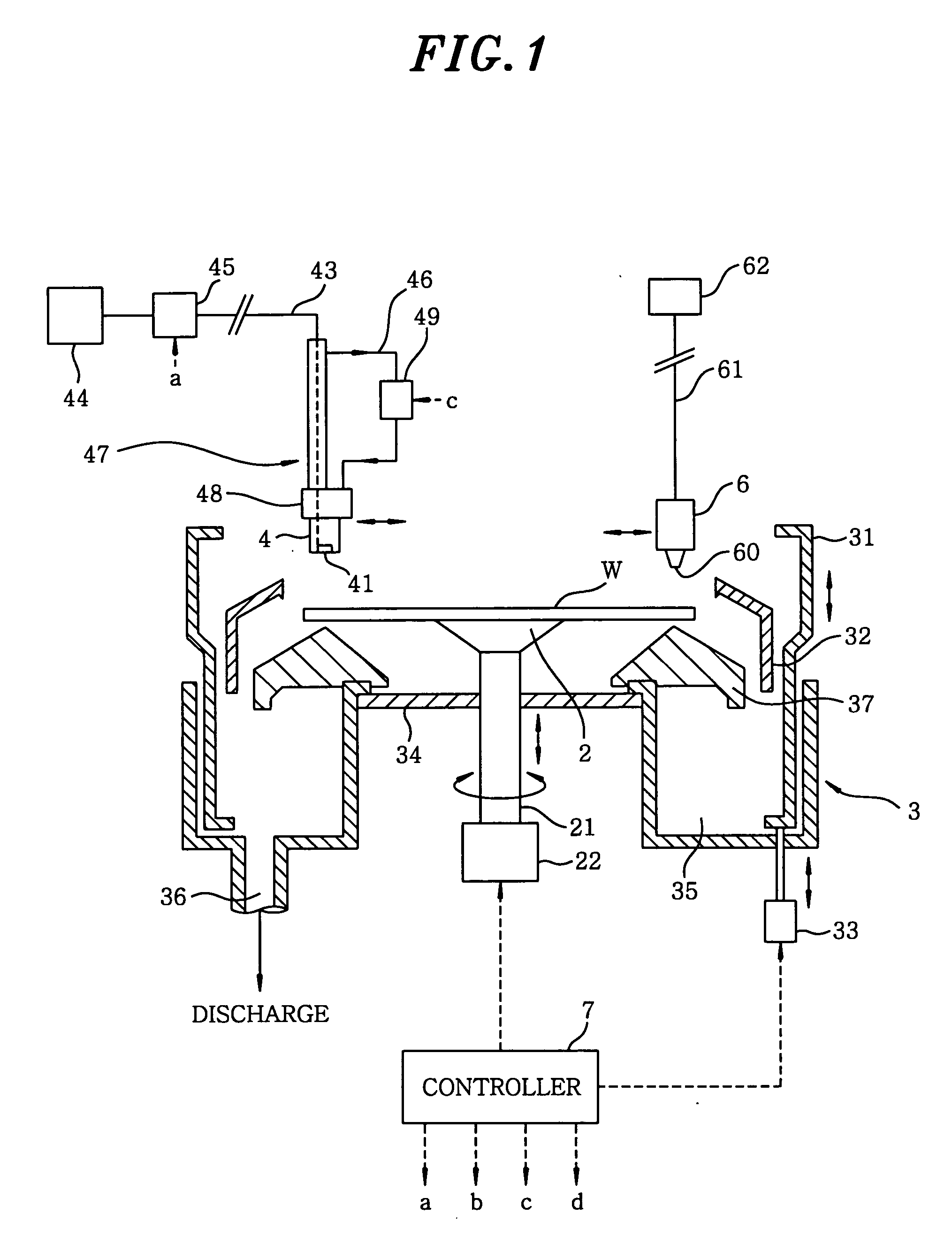
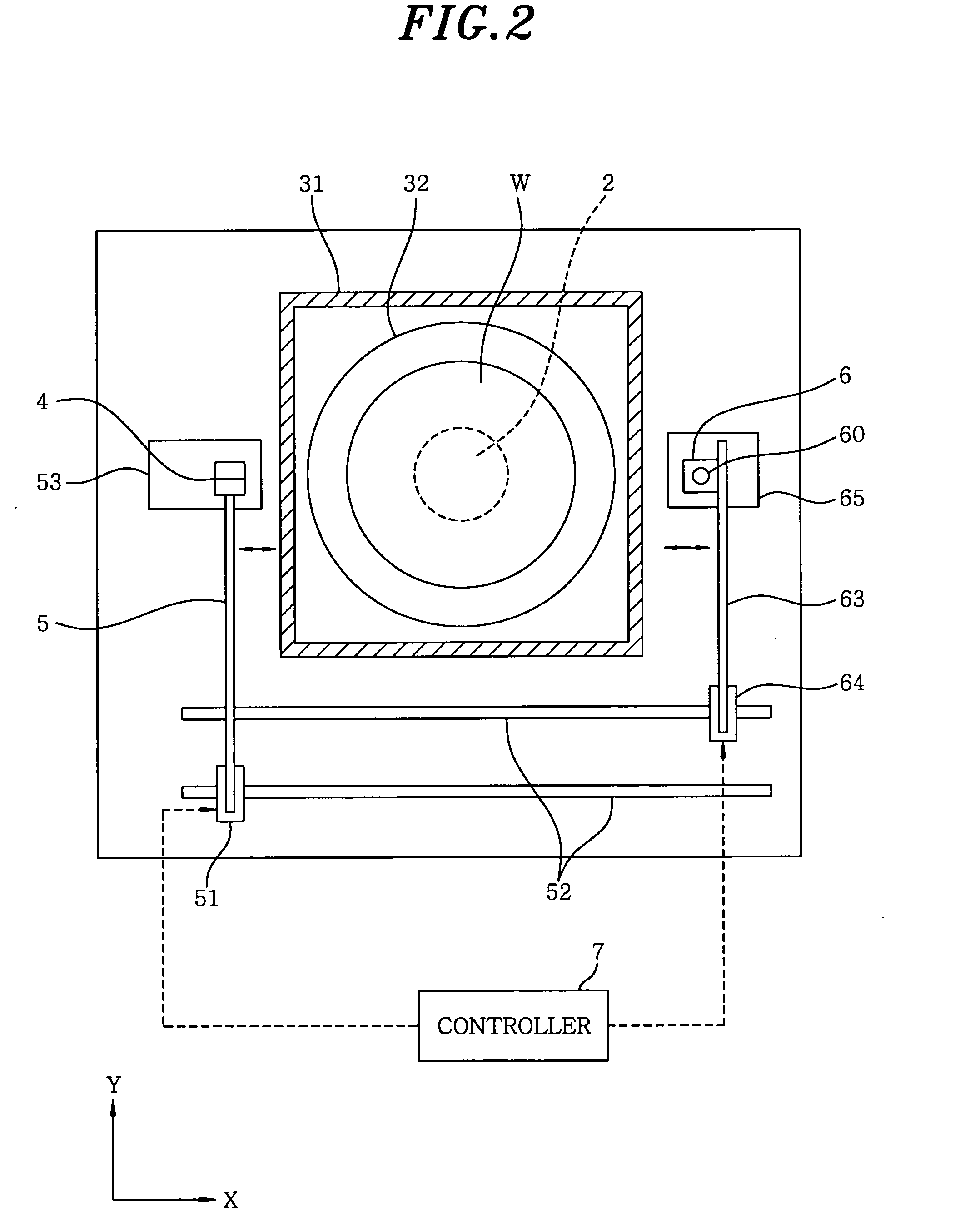
[0038] A developing apparatus in accordance with a preferred embodiment of the present invention will be described with reference to FIGS. 1 and 2. A reference numeral 2 indicates a spin chuck serving as a substrate supporting unit for horizontally supporting a substrate, e.g., a wafer W, by holding a central bottom surface thereof with a help of vacuum adsorption. The spin chuck 2 is connected to a driving mechanism 22, e.g., a motor, forming a rotation driving mechanism via a rotational shaft 21. Further, the spin chuck 2 can be elevated up and down while supporting the wafer W and also pivot on a vertical axis either clockwise or counterclockwise. That is, the spin chuck 2 can be rotated forwardly and backwardly while supporting the wafer W. In addition, a cup body 3 whose upper portion is opened is installed to surround the wafer W supported by the spin chuck 2. In this embodiment, a center of the wafer W is set to be positioned on a rotation axis (a rotation center) of the spin...


PUM


Abstract

A developing apparatus for developing a substrate whose surface is coated with a coating solution and then exposed includes a substrate supporting unit for horizontally supporting the substrate, a rotation driving mechanism for rotating the substrate supporting unit forwardly or backwardly with respect to a vertical axis, a developer nozzle, disposed to face a surface of the substrate supported by the substrate supporting unit, having a strip-shaped injection opening extended along a direction extending from a periphery of the substrate toward a central portion thereof, a moving unit for moving the developer nozzle from an outer portion of the substrate toward the central portion thereof, and a controller for controlling operations such that while the substrate is rotated forwardly by the rotation driving mechanism, a developer is supplied through the injection opening to the surface of the substrate by moving the developer nozzle and, then, the substrate is rotated backwardly by the rotation driving mechanism.

Description

FIELD OF THE INVENTION [0001] The present invention relates to a developing apparatus and method, for developing a surface of a substrate coated with a resist and exposed to light. BACKGROUND OF THE INVENTION [0002] In a photoresist process, one of the semiconductor manufacturing processes, a resist coated on a surface of a semiconductor wafer (hereinafter, referred to as a wafer) is exposed to light by employing a specified pattern and then developed, thereby forming a resist pattern on the surface of the wafer. Such process is generally carried out by using a system in which an exposure device is combined with a coating / developing apparatus for coating and developing a resist. [0003] As illustrated in FIGS. 16A to 16C, for example, in a conventional developing apparatus, a wafer W is horizontally kept on a substrate supporting unit 1, and a developer nozzle 11 having a small injection hole is provided at a position slightly upwardly separated from a surface of the wafer W. By movi...

Claims


Application Information

Patent Timeline
Patent Type & Authority Applications(United States)
IPC IPC(8): B05D5/00
CPCH01L21/6715G03F7/3028
Inventor YAMAMOTO, TAROOOKOUCHI, ATSUSHITAKEGUCHI, HIROFUMIYOSHIHARA, KOUSUKE
Owner TOKYO ELECTRON LTD
Why Eureka
Try Eureka