Fuel cell stack, fuel cell system, and manufacturing method of fuel cell stack

a fuel cell and manufacturing method technology, applied in the field of fuel cell stacks, can solve the problems of increasing the membrane resistance of the fuel cell, reducing the performance of the fuel cell, and reducing so as to reduce the membrane resistance of the electrolyte layer and the effect of easy manufacturing of the fuel cell stack

Inactive Publication Date: 2006-02-23
TOYOTA JIDOSHA KK
View PDF6 Cites 11 Cited by
  • Summary
  • Abstract
  • Description
  • Claims
  • Application Information

AI Technical Summary

Benefits of technology

[0007] In the fuel cell stack of the invention, the integrated structure of the dense inorganic electrolyte layer and the dense base member effectively allows sufficient reduction of the thickness of the electrolyte layer without causing cracks of the electrolyte layer. This arrangement desirably reduces the membrane resistance of the electrolyte layer. The resulting fuel cell stack including high-temperature fuel cells is thus capable of operating in a relatively low working temperature range. Lamination of the multiple unit fuel cells desirably enhances the total power output of the fuel cell stack.
[0024] This manufacturing method of the invention readily manufactures the fuel cell stack having a sufficiently thin electrolyte layer without preventing the occurrence of cracks. This arrangement desirably reduces the membrane resistance of the electrolyte layer. The resulting fuel cell stack including high-temperature fuel cells is thus capable of operating in a relatively low working temperature range.

Problems solved by technology

The cracks appearing in the conventional thin electrolyte layer, however, increases the membrane resistance and undesirably lowers the performance of the fuel cell.
This arrangement desirably reduces the membrane resistance of the electrolyte layer.

Method used


Image

  • Fuel cell stack, fuel cell system, and manufacturing method of fuel cell stack
  • Fuel cell stack, fuel cell system, and manufacturing method of fuel cell stack
  • Fuel cell stack, fuel cell system, and manufacturing method of fuel cell stack

Examples


first embodiment

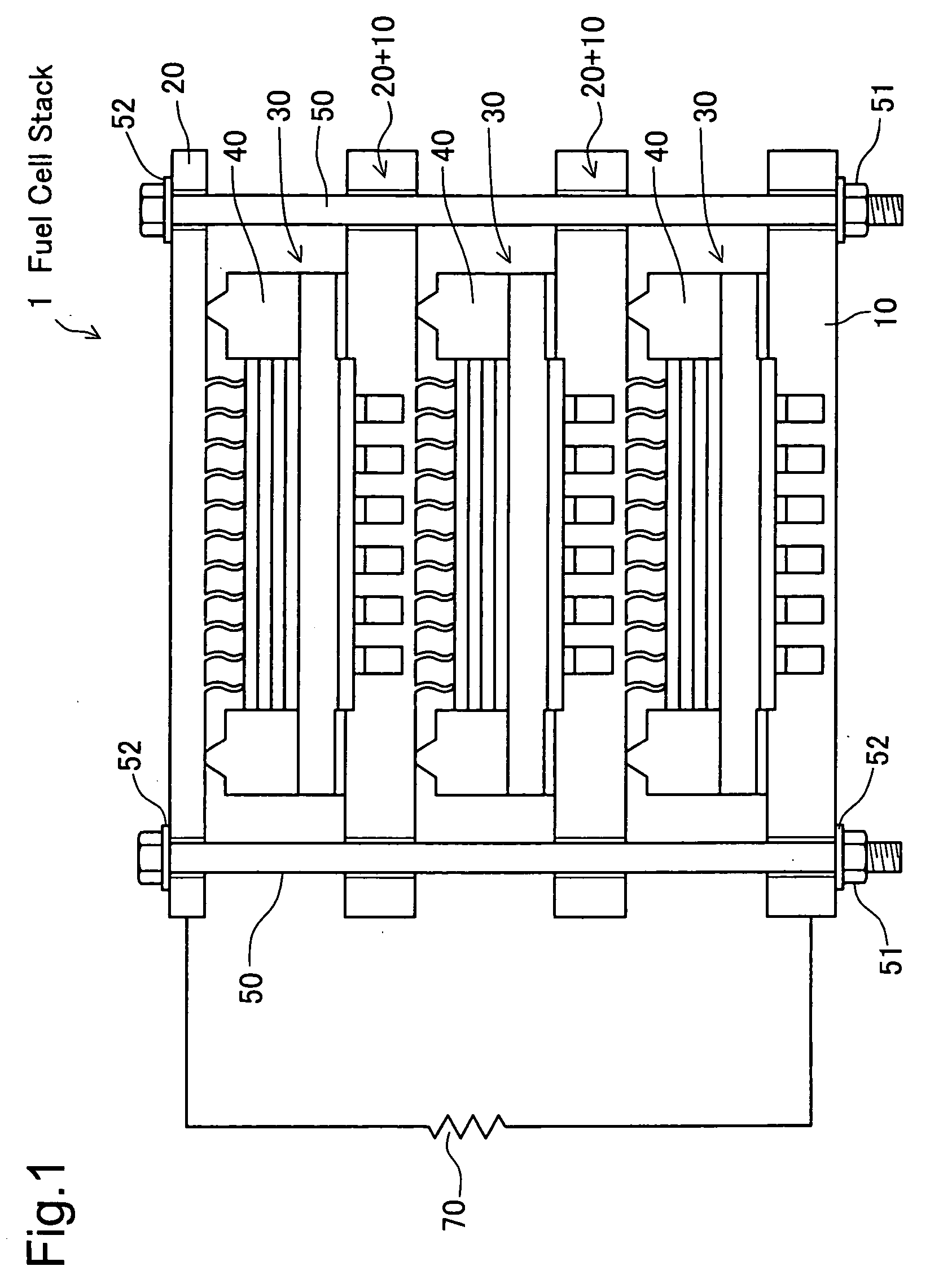
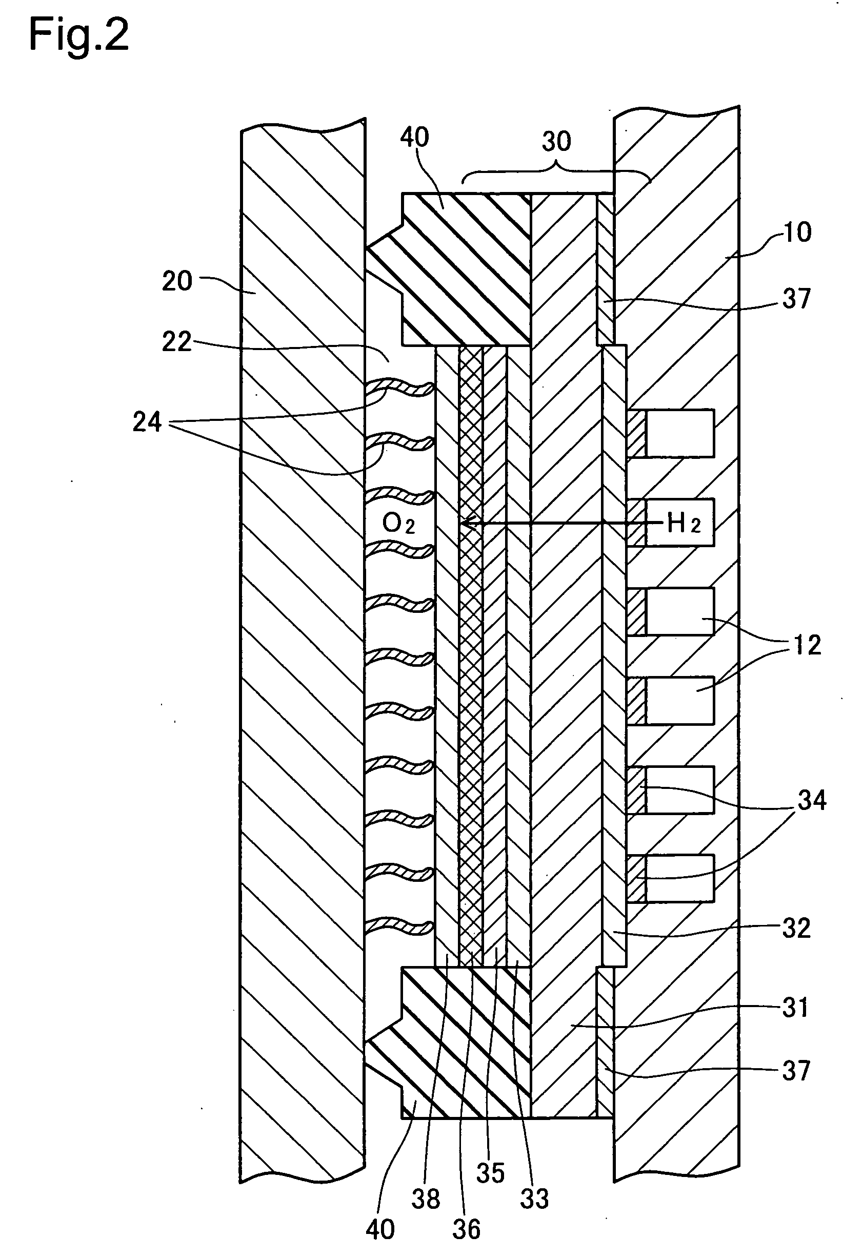
[0037]FIG. 1 schematically illustrates the structure of a fuel cell stack 1 in the invention. FIG. 2 schematically illustrates the structure of each unit fuel cell of the fuel cell stack 1. The unit fuel cell of this embodiment belongs to solid oxide fuel cells. The structure of the unit fuel cell (hereafter referred to as the unit cell) is described first with reference to the sectional view of FIG. 2. The unit cell mainly includes an electrolyte membrane 30 placed between two metal separators 10 and 20.

[0038] One metal separator 10 has a flow path 12 for a supply of hydrogen-rich fuel gas, which includes multiple straight grooves extended in a direction perpendicular to the sheet surface of FIG. 2. The other metal separator 20 has a flow path 22 for a supply of the air as an oxidizing gas. The flow path 22 is formed in a space defined by the metal separator 20, the electrolyte membrane 30, and gaskets 40. The metal separators 10 and 20 are made of a metal material and are preferab...

second modified example

[0074] (b) A second modified example embeds vanadium (V) powder in a punching plate of stainless steel (SUS) and presses the V-embedded punching plate by the hot isostatic pressing technique (HIP) to form a base member. Like the first modified example (a), this modified structure reduces the area of the hydrogen permeable material and makes the hydrogen permeable material surrounded by another metal. This arrangement effectively prevents the potential hydrogen expansion of the base member. The material of the punching plate is not restricted to stainless steel SUS but may be another metal, such as Cu, that is different from the hydrogen permeable material.

[0075] (c) A third modified example envelope-casts vanadium (V) thin wires with SUS and rolls the SUS-cast V thin wires to form a base member. The manufacturing procedure provides a V pin holder, embeds a metal material (for example, SUS or Cu) having a lower melting point than that of V into the gaps of the V pin holder, and casts...

second embodiment

[0091] In the simple structure of the second embodiment, the cooling medium is flowed through the protrusions of the metal separators 10 and 20 in the fuel cell stack 1 to enhance the cooling efficiency. The cooling medium may be switched over to the heating medium according to the requirement. This simple structure thus enhances the activation performance in a cold environment.

[0092] The embodiments and their modified examples discussed above are to be considered in all aspects as illustrative and not restrictive. There may be many modifications, changes, and alterations without departing from the scope or spirit of the main characteristics of the present invention. For example, the electrolyte membrane may be replaced by any of other diverse electrolyte membranes, for example, a polymer electrolyte membrane.


PUM

PropertyMeasurementUnit
thicknessesaaaaaaaaaa

Abstract

The technique of the invention prepares a thin electrolyte layer without causing cracks. An electrolyte membrane 30 includes a dense inorganic electrolyte layer 36 formed on a dense base member 31. Each unit fuel cell includes the electrolyte membrane 30, a fuel electrode, and an oxygen electrode. Multiple unit fuel cells are laminated in series to complete a fuel cell stack.

Description

[0001] This is a Continuation of International Application No. PCT / JP04 / 011015 filed Jul. 27, 2004, which claims the benefit of Japanese Patent Application No. 2003-204734 filed Jul. 31, 2003. The entire disclosure of the prior applications is hereby incorporated by reference herein in its entirety. TECHNICAL FIELD [0002] The present invention relates to a fuel cell stack, a fuel cell system including the fuel cell stack, and a manufacturing method of the fuel cell stack. BACKGROUND ART [0003] A known fuel cell includes a hydrogen separation layer formed on an electrolyte layer of a solid polymer electrolyte membrane as disclosed in JP 10-294117A. The hydrogen separation layer has low gas permeability and controls the amount of gas permeation to a low level even in the presence of holes (hereafter referred to as ‘cracks’) in the electrolyte layer. This structure thus allows a sufficiently thin electrolyte layer. [0004] The cracks appearing in the conventional thin electrolyte layer,...

Claims


Application Information

Patent Timeline
Patent Type & Authority Applications(United States)
IPC IPC(8): H01M8/10H01M2/08H01M8/02H01M8/12H01M8/24
CPCH01M8/0202H01M8/1213H01M8/124Y02E60/525H01M8/2425Y02E60/521H01M8/242Y02P70/50Y02E60/50H01M8/0267H01M8/2432H01M8/2484H01M8/24H01M8/02H01M8/12
Inventor TANO, YUTAKAKIMURA, KENJISATO, HIROMICHINUMATA, KOICHIITO, NAOKI
Owner TOYOTA JIDOSHA KK
Why Eureka
Try Eureka