Separation membrane for direct liquid fuel cell and method for producing the same

a liquid fuel cell and membrane technology, applied in the field of membranes for direct liquid fuel cells, can solve the problems of reducing limiting the reduction of the cost required for fuel cell production, and the inability to reduce the electric resistance of the membrane by thinning, so as to increase the transfer speed of hydroxide ions, increase the water content of the membrane, and the effect of increasing the water conten

Inactive Publication Date: 2011-10-13
TOKUYAMA CORP
View PDF10 Cites 0 Cited by
  • Summary
  • Abstract
  • Description
  • Claims
  • Application Information

AI Technical Summary

Benefits of technology

[0057]Introduction of a hydrophilic hydroxy group into an anion-exchange resin leads to increase in a water content of a membrane. However, increase of a water content is not so high as in the case of introduction of a highly hydrophilic anion-exchange group. In general, when a water content is increased in an ion-exchange resin, an increase rate in a transfer speed of hydroxide ions in the ion-exchange resin is larger than that of methanol. Therefore, introduction of a hydroxy group into an ion-exchange resin can effectively reduce a membrane resistance without significantly increasing fuel permeability through a membrane.
[0058]As described above, by properly increasing a cross-linking degree of the ion-exchange resin, adjusting the amount of introducing anion exchange groups and introducing a hydroxy group into the ion-exchange resin, a membrane having improved characteristics as a membrane into which the above hydrophobic group is introduced can be obtained.
[0059]A direct liquid fuel cell having a membrane produced by a manufacturing process of the present invention has a low internal resistance of the cell and reduced cross-over of a liquid fuel such as methanol. As a result, a direct liquid fuel cell having this membrane has a higher cell output.

Problems solved by technology

Furthermore, a perfluorocarbon sulfonic acid resin membrane is expensive, so that there is a limit on reducing a cost required for producing a fuel cell.
(ii) Since a perfluorocarbon sulfonic acid resin membrane is insufficiently water-retentive, water must be supplied during operating a fuel cell.
(iii) Since a perfluorocarbon sulfonic acid resin membrane is not physically strong, an electric resistance cannot be reduced by thinning a membrane.

Method used


Image

  • Separation membrane for direct liquid fuel cell and method for producing the same
  • Separation membrane for direct liquid fuel cell and method for producing the same
  • Separation membrane for direct liquid fuel cell and method for producing the same

Examples


examples

[0177]There will be specifically described the present invention with reference to Examples, but the present invention is not limited to these examples in any manner.

[0178]In Examples and Comparative Examples, an anion-exchange capacity, a water content, a membrane resistance and a methanol permeability of a membrane (anion-exchange membrane) and a fuel cell output voltage were determined for evaluating properties of a membrane for a fuel cell. The methods for determining these will be described below.

1) Determination of an Anion-Exchange Capacity and a Water Content

[0179]An ion-exchange membrane was immersed in a 0.5 mol / L aqueous solution of NaCl for 10 or more hours to be converted to a chloride ion type. Then, the ion-exchange membrane was converted to a nitrate ion type by a 0.2 mol / L aqueous solution of NaNO3, and chloride ions liberated during the process were quantified with an aqueous silver nitrate using a potentiometric titrator (COMTITE-900, Hiranuma Sangyo Co., Ltd.) (A...

examples 1 to 9

[0185]In accordance with the formulation shown in Table 1, monomers and others were mixed to prepare a monomer composition. In any system, an epoxy compound (trade name: EPOLIGHT 40E, Kyoeisha Chemical Co., Ltd.) as a hydrogen-chloride scavenger was added in 5% by weight to the total amount of the monomer mixture. Then, 400 g of the monomer composition thus prepared was placed in a 500 mL glass vessel, and the porous membrane (made of a polyethylene having a weight-average molecular weight of 250,000, film thickness: 25 μm, average pore size: 0.03 μm, porosity: 37%) shown in Table 1 was immersed in the monomer composition for 5 min.

[0186]The porous membrane was removed from the monomer composition, and both sides of the porous membrane was covered using a polyester film with a thickness of 100 μm as a release material, and then the product was heated under a nitrogen pressure of 3 kg / cm2 at 80° C. for 5 hours to polymerize the monomers.

[0187]The membraneous resin cured product thus ...

examples 10 and 11

[0189]In accordance with the formulation shown in Table 1, monomers and others were mixed to prepare a monomer composition. Using the monomer composition, a membraneous resin cured product was prepared as described for the first manufacturing process.

[0190]In a 500 mL glass vessel were placed 100 mL of a 3 mol / L aqueous solution of sodium hydroxide and 100 mL of methanol. The resin cured product prepared was immersed in this mixed solution and was reacted in a closed system at 50° C. for 24 hours, converting acetoxy to hydroxy.

[0191]After the reaction, the resin cured product having the converted hydroxy group was immersed in an aqueous solution of 6% of trimethylamine and 25% of acetone at room temperature for 16 hours, to give a membrane for a fuel cell. This membrane was immersed in a 0.5 mol / L aqueous sodium hydroxide solution at 25° C. for 5 hours for replacing the counter ions of the anion-exchange group with hydroxide ions, and then the product was left for 10 hours or more i...


PUM

PropertyMeasurementUnit
pore sizeaaaaaaaaaa
sizeaaaaaaaaaa
porosityaaaaaaaaaa

Abstract

Disclosed is a method for producing a membrane for direct liquid fuel cells, wherein a polymerizable composition is brought into contact with a porous membrane so that voids of the porous membrane are filled with the polymerizable composition, then the polymerizable composition is cured by polymerization, and after that a halogenoalkyl group in the resin membrane is converted into a quaternary ammonium group. In this method, the polymerizable composition contains (a) an aromatic polymerizable monomer having an aromatic ring wherein one polymerizable group, at least one halogenoalkyl group and a group which is inert to a reaction converting the at least one halogenoalkyl group into a quaternary ammonium group, are bonded together, (b) a crosslinkable polymerizable monomer and (c) a polymerization initiator.

Description

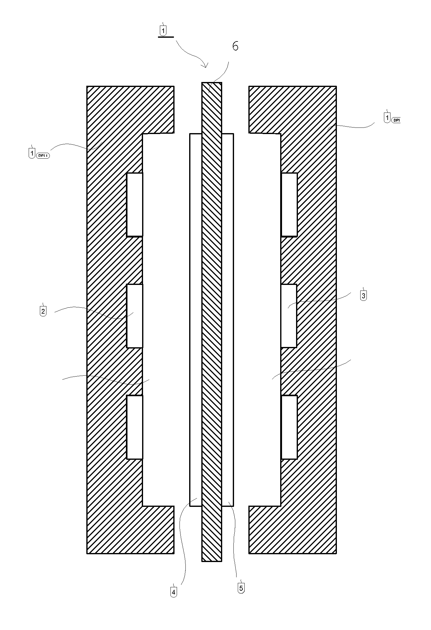
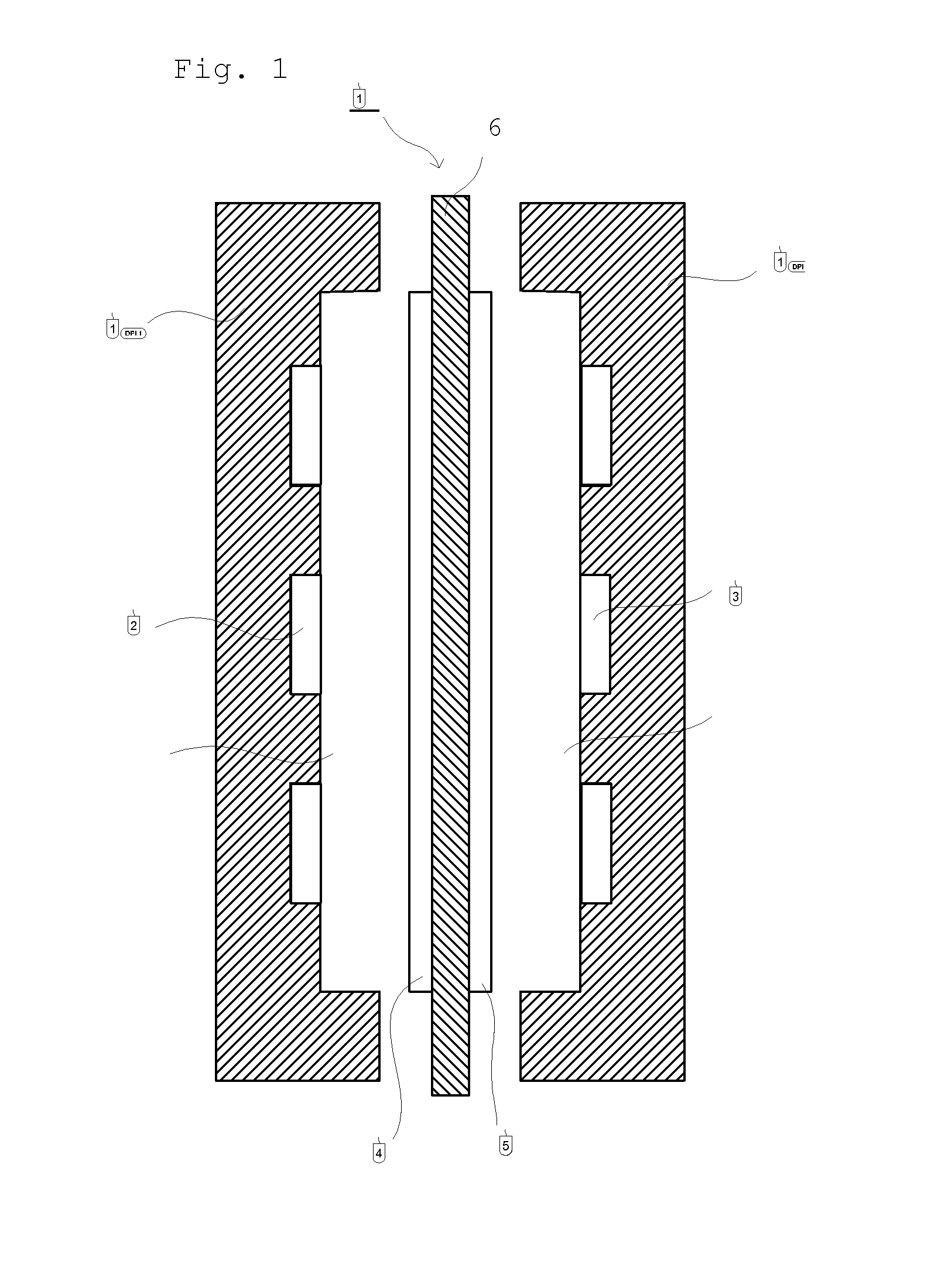
TECHNICAL FIELD[0001]The present invention relates to a membrane for a direct liquid fuel cell and a manufacturing process therefor. In the membrane, a resin constituting the membrane has an aromatic ring having a particular functional group at a predetermined position. The membrane has a feature of reduced permeability of a liquid fuel such as methanol.BACKGROUND OF THE INVENTION[0002]A polymer electrolyte fuel cell is a fuel cell using a solid polymer such as an ion-exchange resin as an electrolyte. This fuel cell is characterized in that an operation temperature is relatively lower.[0003]The polymer electrolyte fuel cell has a basic structure as shown in FIG. 1, where a space inside of cell partition walls 1a and 1b is divided by an assembly 10. The assembly 10 comprises a solid polymer electrolyte membrane 6, to whose sides a fuel diffusion electrode 4 and an oxidizing agent diffusion electrode 5 are attached, respectively. The assembly 10 divides the space inside of the cell pa...

Claims


Application Information

Patent Timeline
Patent Type & Authority Applications(United States)
IPC IPC(8): H01M8/10H01M8/00
CPCC08J5/2275H01M8/1009H01M8/1023H01M8/1072Y02E60/521C08J2325/08C08F2810/20C08F2800/20C08F8/44C08F212/14C08F212/36Y02P70/50Y02E60/50C08F212/18C08F212/21
Inventor ISOMURA, TAKENORIFUKUTA, KENJI
Owner TOKUYAMA CORP
Why Eureka
Try Eureka