Measurement element position determination

a technology of measurement elements and positions, applied in the direction of diagnostic recording/measuring, application, impression caps, etc., can solve problems such as registration and/or other accuracy problems

Inactive Publication Date: 2006-02-23
TACTILE TECH
View PDF36 Cites 11 Cited by
  • Summary
  • Abstract
  • Description
  • Claims
  • Application Information

AI Technical Summary

Benefits of technology

[0005] An aspect of some embodiments of the invention relates to determining the surface structure or internal structure of an object. The object could be organic, such as a mandible, knee or spinal cord, or inorganic. Various measurement elements can be utilized, either penetrating or non-penetrating depending on the surface to be measured, in conjunction with at least one position encoder to collect position data points which wh...

Problems solved by technology

The multiple position determination may ca...

Method used


Image

  • Measurement element position determination
  • Measurement element position determination
  • Measurement element position determination

Examples


Embodiment Construction

General Description of an Exemplary Embodiment

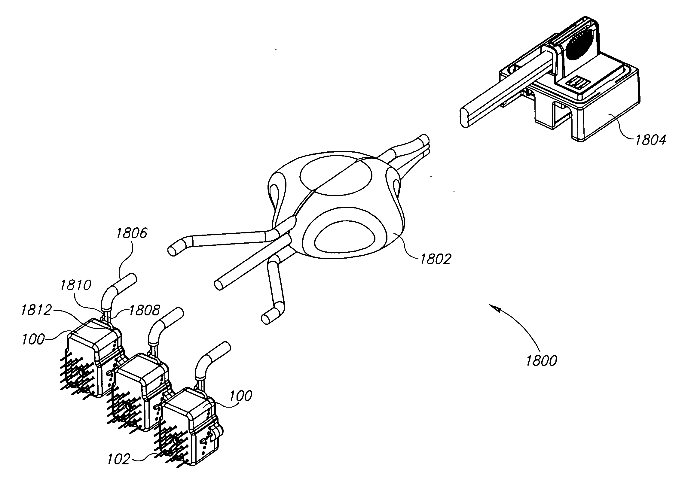
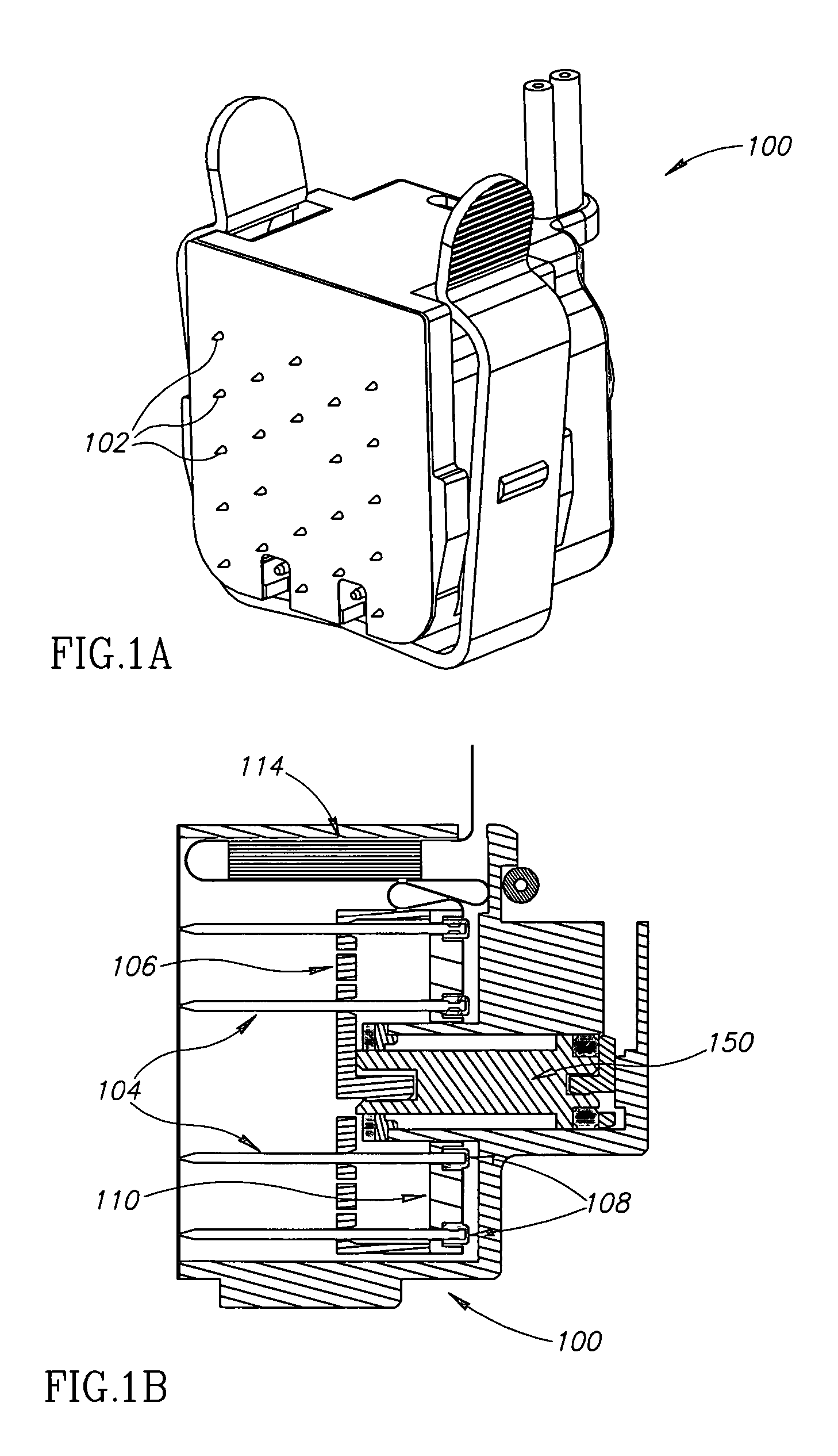
[0046] Referring to FIG. 18, a schematic showing an overall system 1800 for determining measurement element positions is shown. Measurement elements 102 are depicted protruding out of a cartridge assembly 100 generally in the direction of an object whose surface geometry is to be measured. Measurement elements 102 and cartridge assembly 100 are described in greater detail below. A control module 1804 is provided in operative communication with at least one cartridge assembly 100. In some exemplary embodiments of the invention, communication comprises data generated by at least one cartridge assembly 100. Optionally, communication comprises data generated by control module 1804. Optionally, communication is achieved via electronics. In some exemplary embodiments of the invention, communication is comprised of movement impetus generated at control module 1804. Optionally, communication is achieved via hydraulics. Optionally, communication...


PUM


Abstract

An apparatus for determining measurement element positions, comprising a plurality of measurement elements; at least one trigger element corresponding to each element of the plurality of measurement elements; a positional encoder configured to register a position of each of the measurement elements when the trigger element is activated; and a controller, wherein the controller constructs a surface geometry model from the registered measurement element positions.

Description

RELATED APPLICATIONS [0001] The present application is a continuation-in-part of PCT Application No. PCT / IL2004 / 000069, filed on Jan. 23, 2004, and a continuation-in-part of PCT / IL2004 / 000062, filed on Jan. 22, 2004, which is a continuation-in-part of U.S. application Ser. No. 10 / 350,288, filed Jan. 23, 2003, the disclosures of all of which are incorporated herein by reference.FIELD OF THE INVENTION [0002] The present invention relates to the determination of measurement element positions, for example for the measurement of surface geometries. BACKGROUND OF THE INVENTION [0003] There are many applications where knowing the surface structure or internal structure of an object is desirable. A typical solution for ascertaining hard tissue surface structure, especially if the tissue is hard and is underlying soft tissue as is the case in dental care, is to obtain X-Ray CT images of the hard tissue to construct a model based on the images. [0004] Another methodology for determining the s...

Claims


Application Information

Patent Timeline
IPC IPC(8): A61C19/04A61B17/17A61B19/00A61C1/08A61C9/00
CPCA61B5/103A61C9/0046A61B5/4504A61B17/17A61B17/176A61B19/201A61B19/46A61B19/54A61B2019/303A61B2019/461A61B2019/463A61B2019/5425A61B2019/5437A61B2562/046A61C1/084A61C19/04A61B5/6862A61B5/6878A61B5/1077A61B5/407A61B2090/033A61B2090/063A61B90/11A61B90/06A61B2090/061A61B90/39A61B2090/3925A61B2090/3937A61B2562/17
Inventor WEINSTEIN, URIELKINROT, OPHERBERNSTEIN, ASSAFSLOVIN, ZVIKA
Owner TACTILE TECH
Why Eureka
Try Eureka