Stationary vehicle air conditioning system and method

a technology for stationary vehicles and air conditioning systems, which is applied in the direction of indirect heat exchangers, compression machines with several condensers, light and heating apparatus, etc. it can solve the problems of cooling systems that typically require undesirable charging time and components that do not permit optimal operation of cooling systems, and achieve optimal utilization, simple regulation, and available energy

Active Publication Date: 2006-03-02
BEHR GMBH & CO KG
View PDF19 Cites 48 Cited by
  • Summary
  • Abstract
  • Description
  • Claims
  • Application Information

AI Technical Summary

Benefits of technology

[0005] A stationary vehicle air conditioning system with a refrigerant circuit is provided. The circuit includes at least one compressor, which circulates refrigerant within the circuit and which can be driven with an electrical or a mechanical source. An air cooled condenser for cooling the refrigerant coming from the compressor is also arranged in the circuit. In a preferred embodiment of the invention, two fans are provided, each of which provides an air stream in a different vehicle operating mode. One fan is driven mechanically with the aid of the vehicle engine, and the other fan is driven electrica

Problems solved by technology

This arrangement of components does not permit the systems to operate in an optimal manner.
Other types of stationary air conditioning

Method used


Image

  • Stationary vehicle air conditioning system and method
  • Stationary vehicle air conditioning system and method
  • Stationary vehicle air conditioning system and method

Examples


first embodiment

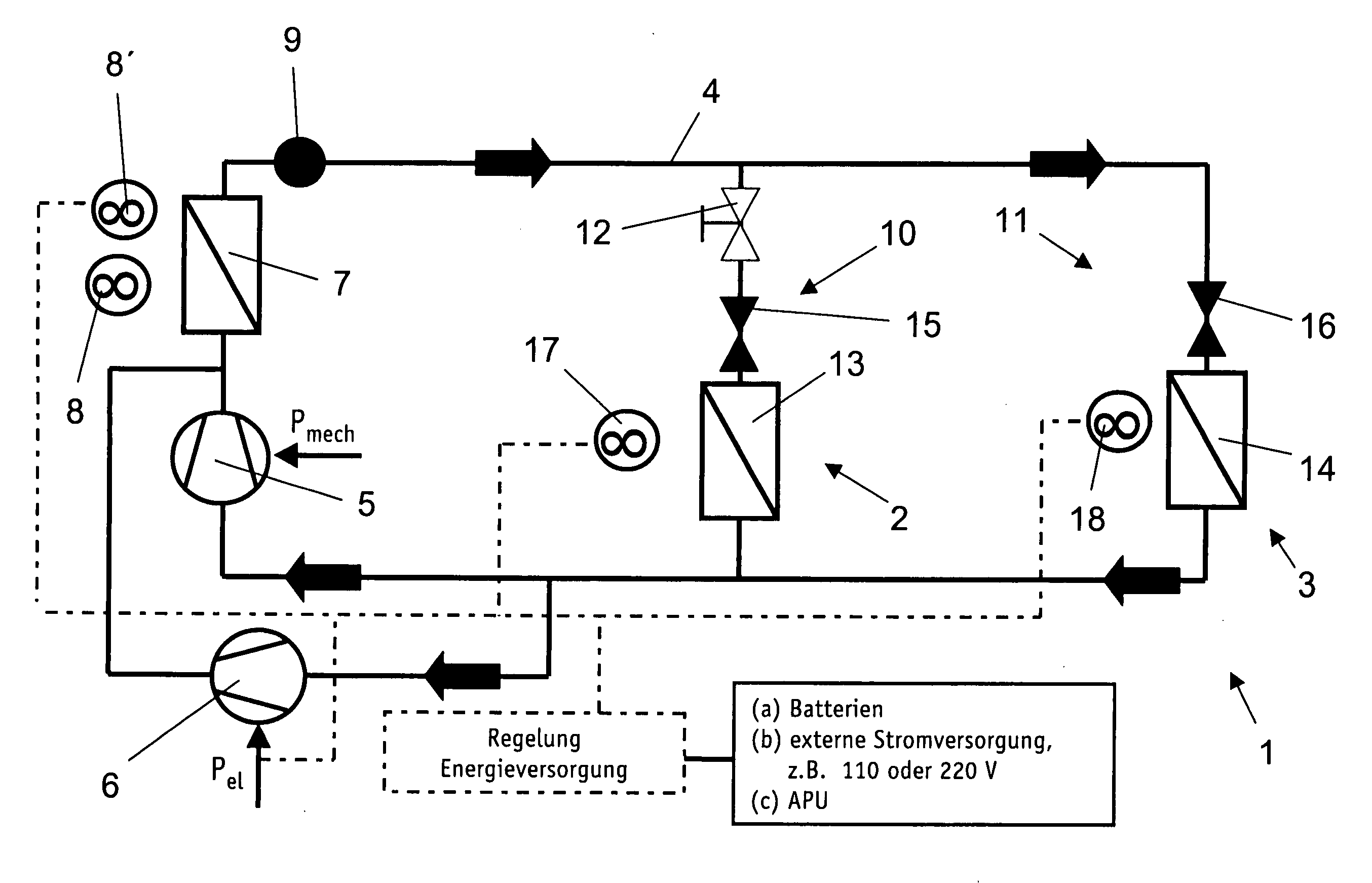
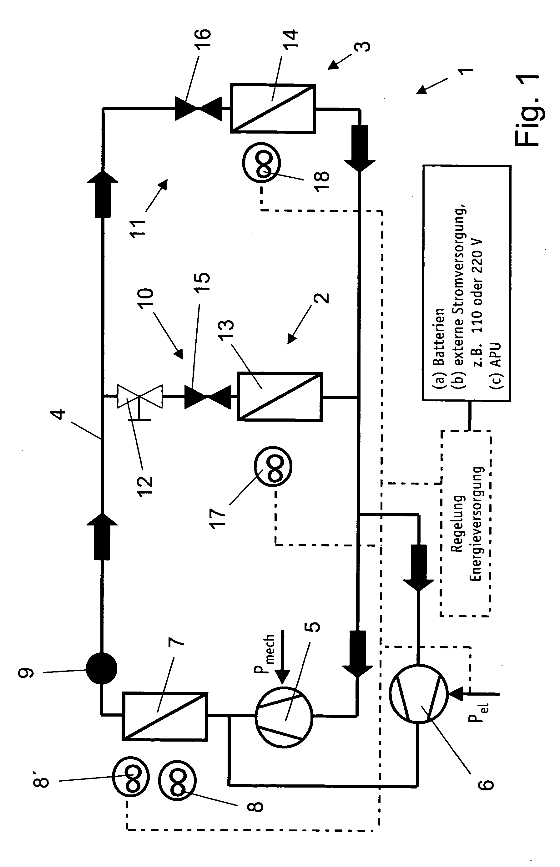
[0032] In the invention, as illustrated in FIG. 1, two compressors 5 and 6 are arranged in parallel branches of refrigerant circuit 4. In order to prevent backflow when second compressor 6 is not running, a check valve (not shown) is arranged in the corresponding branch of refrigerant circuit 4, downstream of second compressor 6 in the direction of refrigerant flow. A matching check valve can also be provided in the other branch downstream of first compressor 5.

[0033] The flow of refrigerant through circuit 4 in “normal” operation, i.e., with the vehicle's engine running, will be described first. Compressor 5 drives refrigerant, which is hot as a result of compression, through a condenser 7 that is cooled by air via a first vehicle-engine driven fan 8. Condenser 7 may be further cooled by wind or by an air stream generated through the motion of the vehicle. Downstream of condenser 7, a receiver 9 collects and temporarily stores excess liquid refrigerant.

[0034] As illustrated in FIG...

third embodiment

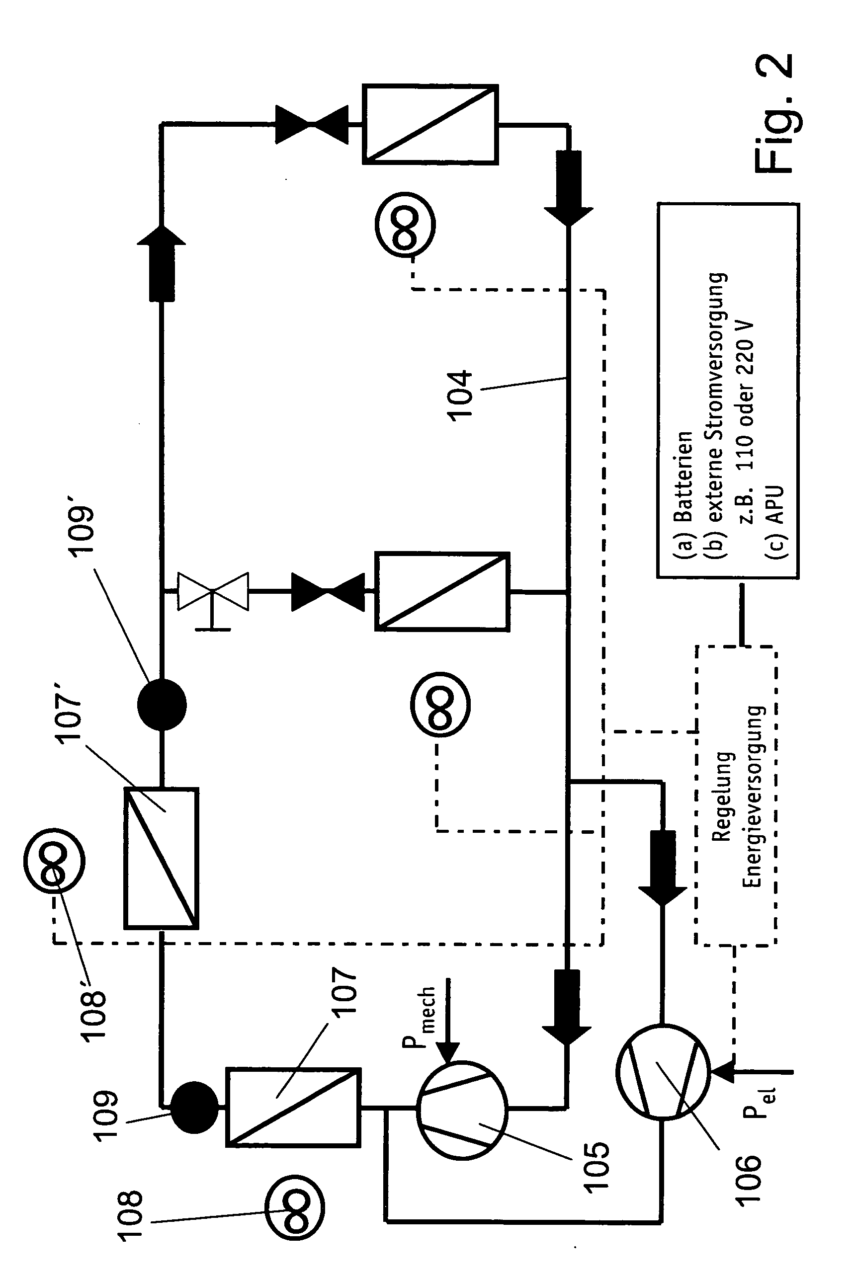
[0040] the invention, which is illustrated in FIG. 3, overlaps with the previously described embodiments as will be appreciated by persons of skill in the art. Unlike the embodiment of FIG. 2, however, a bypass branch is provided downstream of a first condenser and receiver 209. In a normal operating mode, the valve upstream of second condenser 207′ is closed and the valve in the bypass is open. The second condenser 207′ is thus effectively removed from the refrigerant circuit due the diversion of refrigerant. When switched to a second operating mode, such as when the vehicle engine stops running, the valve upstream of second condenser 207′ is opened and the other valve is closed, thereby closing the bypass and forcing refrigerant to flow through second condenser 207′ and second receiver 209′. In this latter mode of operation, fan 208 is inactive, but second fan 208′ supplies an air stream to condenser 207′ for heat transfer purposes.

[0041]FIG. 4 illustrates a fourth embodiment of t...

seventh embodiment

[0042] In the invention, as illustrated in FIG. 7, the refrigerant circuit 604 can be selectively divided by means of valves 620, 621 into a refrigerant circuit 604a for front air conditioner 602 and a refrigerant circuit 604b for rear air conditioner 603. An electrical source provides power to electrically drivable compressors 606a and 606b. Condensers 607a, 607b are respectively arranged downstream of each compressor. The separation of the larger circuit 604 into two sub-circuits by means of the valves 620, 621 allows optimized cooling to fit the need, particularly in stationary operation.

[0043] In a first and normal operating mode, valves 620, 621 are opened, and compressor 606a circulates refrigerant through circuit 604. Appropriate sensors, switches and control logic (not shown) detect and select the position of valves 620, 621, as well as the operation of compressor 606b, which remains inactive in this mode of operation. Compressor 606a drives refrigerant through condenser 607...


PUM


Abstract

The invention pertains to a stationary vehicle air conditioning system with a refrigerant circuit, in which a compressor circulates refrigerant through a refrigerant circuit including at least one condenser. The one compressor may be powered by the vehicle's mechanical power, by an electrical source, or by a combination of these driving forces. Depending on desired operating characteristics, a plurality of condensers may be arranged in a series or parallel configuration within the circuit, and a second compressor also may be added, which second compressor may be powered by a source other than the mechanical energy of the vehicle's engine. A plurality of fans may be positioned and selectively operable to provide cooling air streams to one or more of the condensers, with the vehicle engine mechanically driving one fan and an electrical power source driving another fan. At minimum, at least one fan is provided to provide a cooling air stream to one or more condensers, wherein the fan is a hybrid drive unit that is capable of being driven through mechanical or electrical means.

Description

CROSS-REFERENCE TO RELATED APPLICATIONS [0001] This patent application claims the benefit of German Patent Application No. DE 10 2004 042 679.1, filed Sep. 1, 2004, which is hereby incorporated by reference. FIELD OF THE INVENTION [0002] The invention pertains to a vehicle air conditioning system and method, and more particularly, to an air conditioning system that is particularly advantageous for use with a vehicle in which the engine is not running (a “stationary vehicle”). The invention may be employed, for example, with a truck having a first air conditioner in the driver's compartment and a second air conditioner in a sleeping compartment. The air conditioning system and method includes a plurality of components that may be operated in a first mode while the engine is running and in a second mode while the engine is not running. BACKGROUND OF THE INVENTION [0003] German patent application DE 44 14 547 A1 describes a stationary vehicle air conditioning system in which the vehicl...

Claims


Application Information

Patent Timeline
IPC IPC(8): F28D5/00B60H1/32F25B27/00F25B39/04F25B1/10
CPCB60H1/00428B60H1/00457B60H1/323F25B5/02F25B2400/075F25B6/02F25B6/04F25B49/027F25B2400/0403F25B6/00
Inventor HEBERLE, ARTHURWEINBRENNER, MARCUS
Owner BEHR GMBH & CO KG
Why Eureka
Try Eureka