Device and method for adjusting a position of an eyeglass lens relative to the position of a pupil

Inactive Publication Date: 2006-03-02
CARL ZEISS VISION INT GMBH
11 Cites 29 Cited by

AI-Extracted Technical Summary

Problems solved by technology

A disadvantage of the prior art systems is that faulty measurements relating to the exact position of the pupil centers may occur when the recorded image ha...

Benefits of technology

[0016] By illuminating the eye portion of the person with a light from the specified wavelength range the retina of the eye is caused to reflect such light so that it distinguishes from the surrounding iris at high contrast. The use of a camera optimized for this wavelength has the advantage that particular clear and high contrast images may be obtained even at low light intensity.
[0017] The optometrist is therewith enabled to reliably determine the position of the pupil centers by manual marking with the cursor. However, it is stil...

Abstract

An apparatus and a method are used for adapting a position of at least one spectacle lens of a spectacle relative to the position of a pupil of an eye of a person, the eye being associated to the spectacle lens. The apparatus comprises an illuminating device for an eye area of the person wearing a spectacle frame that is not yet fitted with lenses. Further, at least one camera for generating an image of the eye area is provided. The position of the pupil within the image is marked. The illuminating device has at least one light source operating within a wavelength range the light of which being reflected by the retina of the eye at a high ratio of reflection. The camera in its sensitivity is optimized to the wavelength of the light emitted by the light source.

Application Domain

Spectales/gogglesEye diagnostics

Technology Topic

Wavelength rangeLight source +6

Image

  • Device and method for adjusting a position of an eyeglass lens relative to the position of a pupil
  • Device and method for adjusting a position of an eyeglass lens relative to the position of a pupil
  • Device and method for adjusting a position of an eyeglass lens relative to the position of a pupil

Examples

  • Experimental program(1)

Example

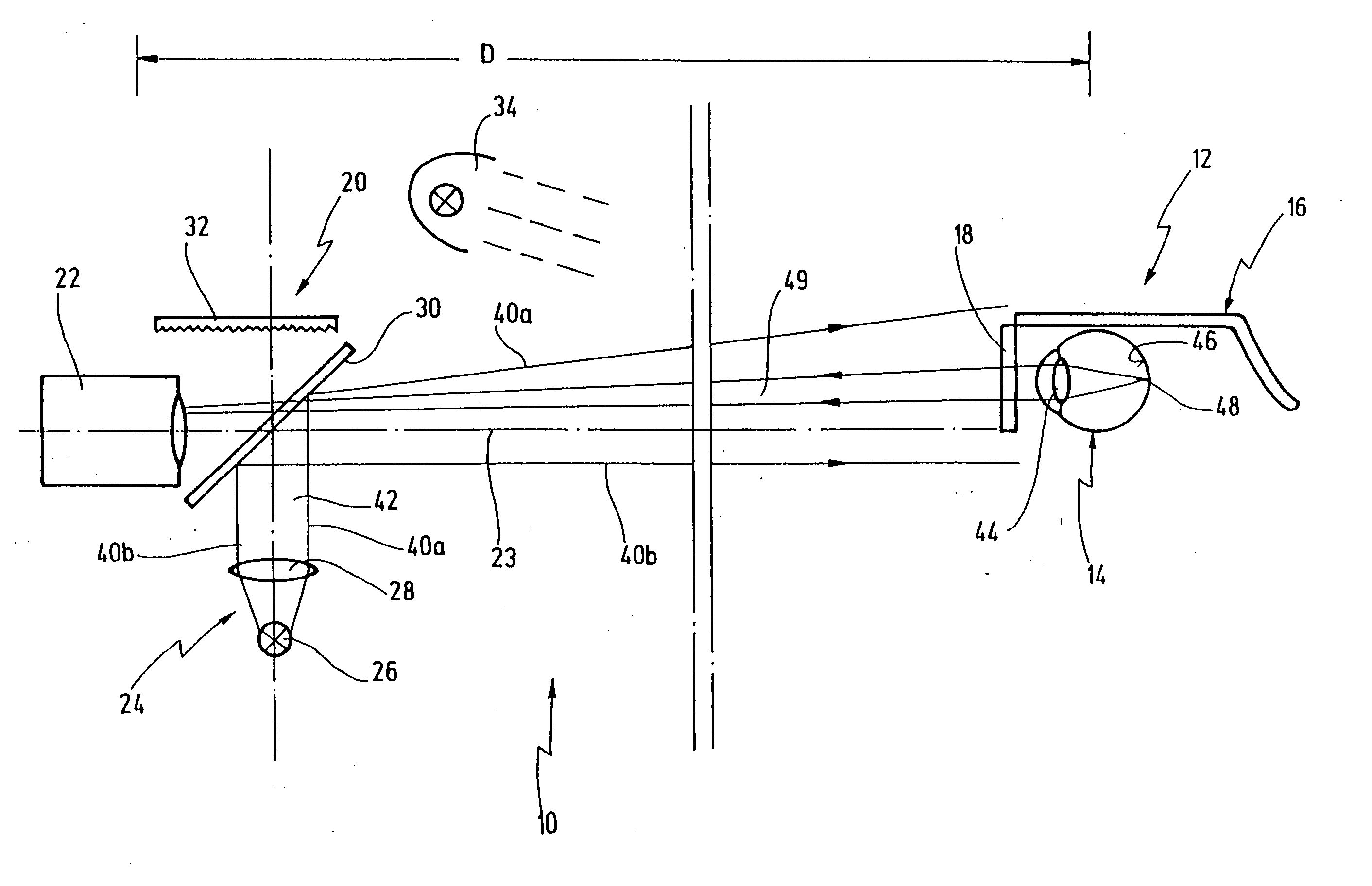
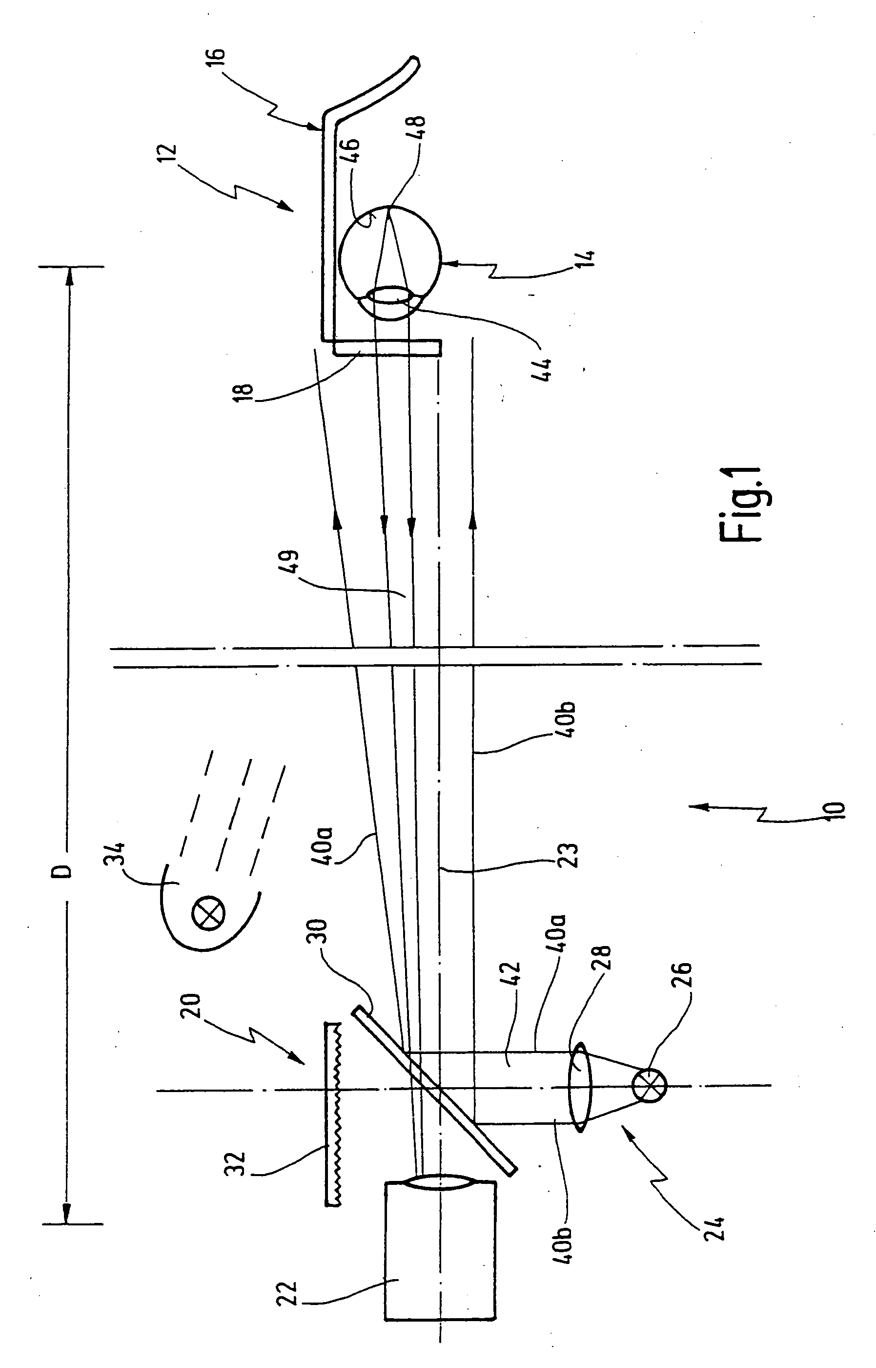
[0058] In FIG. 1 reference numeral 10 as a whole indicates an apparatus for adapting a position of at least one spectacle lens, in particular of a progressive power lens, of a spectacle relative to the position of a pupil of an eye of a person, the eye being associated to the spectacle lens.
[0059] In FIG. 1 the person as a whole is indicated at 12, only an eye 14 and a spectacle 16 or spectacle frame 18, resp., being shown.
[0060] A recording system indicated as a whole at 20 is located at a distance D of several meters, preferably two to eight meters.
[0061] Recording system 20 comprises a camera 22, the optical axis of which is designated with reference numeral 23.
[0062] An illumination device 24 is provided under a right angle relative to axis 23. Illumination device 24 comprises a light source 26, in particular a light diode (LED) operating in the red or the infrared range. Light source 26 has a lens 28 associated thereto. Light source 26 is directed onto a beam splitter 30. A light trap 32 is arranged on the opposite side of beam splitter 30.
[0063] Finally, recording system 20 comprises a general illumination device 34 with conventional white light.
[0064] In FIG. 1, reference numerals 40a and 40b indicate marginal rays of light 42 emitted by light source 26. Light 42 and marginal rays 40a, 40b, resp., are reflected at beam splitter 30 and are directed onto eye 14 of person 12. Light 42 enters eye 14 via an eye lens 44 and impinges on a retina 46 on which an image 48 is generated. If person 12 has normal vision, image 48 is a focussed image, whereas if person 12 has defective vision, an unfocussed image is generated, as will be explained.
[0065] Reference numeral 49 designates a light being remitted by retina 46. Light 49, in turn, impinges on beam splitter 30 and partially falls into camera 22.
[0066] Beams splitter 30 is preferably configured as a partially transparent mirror. It consists of a transparent plane-parallel plate, e.g. made from glass, one side of which being unprocessed or partially reflective and the other side of which being dereflected.
[0067] The mirror may have a degree of reflection of 50%. With that selection of the degree of reflection a maximum of remitted light 49 would be directed into camera 22. Light 42 emitted by light source 26 namely is reflected with the same degree of reflection by the mirror, is directed towards eye 14 and is there remitted. Remitted light 49 with its fraction being transmitted through beam splitter 30 falls into camera 22.
[0068] From an energetic point of view a degree of selection of 50% would, therefore, be optimal. For practical reasons, however, one strongly deviates from that value and uses a degree of reflection being of the order of between 8% and 40%.
[0069] Moreover, it is preferred to select a mirror coating having advantageously a still lower degree of reflection for wavelengths at which light 42 has no or a small intensity. Degrees of reflection being smaller than those 50% mentioned are, moreover, particularly helpful because one must also detect the spectacle frame 18 in front of the face of person 12. If person 12 has a dark colored skin, the advantage of this measure is particularly great.
[0070] As has already been mentioned, light source 26 preferably is a light diode operating in the red or the infrared range. Instead of one single light diode one may alternately also use a bundle of such diodes, however, lens 28 would then have to be configured as a corresponding honeycomb structure, as known per se.
[0071] Light trap 32 being only schematically indicated in FIG. 1 is provided for absorbing light 42 having run through beam splitter 30 unreflected. One might use a black cardboard, a soot-covered sheet metal or a surface to which a black velvet is glued as light trap 32. Such a light trap might also be configured as a so-called “black bag”.
[0072]FIG. 3 shows an image 60 recorded by camera 22. One can see an eye area 61 of person 12. A right pupil and a left pupil of person 12 are designated 62r, 62l, a respective corresponding iris 64r, 64l. The center of each iris 64r, 64l is inserted in FIG. 3 as a cross of two dash-dot lines.
[0073] Reference lines for spectacle frame 18r and 18l, resp., are entered as vertical lines 66r, 66l and as horizontal lines 68r, 68l.
[0074] One may clearly see from FIG. 3 that the exact position of the center of each iris 64r, 64l as well as the exact position of spectacle frames 18r and 18l may be also automatically detected from image 60 by means of conventional image processing methods. In any event it is manually possible to simply identify these points and lines, resp., by means of a cursor and to mark same in image 60.
[0075] Due to the selected wavelength of light 42 retina 46 behind pupils 62r and 62l shines brightly such that pupils 62r, 62l clearly contrast from the respective surrounding iris 64r and 64l, resp. This holds also and particularly true when iris 64r, 64l is relatively dark by itself.
[0076]FIG. 4 shows the circumstances with a person 12 having accommodated on a short distance, e.g. until point 70, in particular because person 12 is short-sighted. At point 70 there is a real image of retina 46 within eye 14.
[0077] In order to be able to conduct a successful measurement also in that case, the embodiment of FIG. 2 is used in which additional light sources 50a, 50b are arranged about axis 23, in particular in a ring-shaped configuration. Marginal rays 52a, 52b shown in FIG. 2 characterize the light emitted by additional light sources 50a, 50b. This light runs towards the pupil centers of the person. Due to the defective vision unfocussed images of additional light sources 50a, 50b are generated on retina 46 of eye 14. The intensity distributions around the geometric projection points along marginal rays 52a, 52b are schematically depicted in partial illustrations 72a through 72c at the right hand side of FIG. 4. Of course, in FIG. 4 the angles between marginal rays 52a, 52b and axis 23 are shown highly exaggerated and much bigger than in reality.
[0078] As one can take from partial illustrations 72a through 72c, the margins of external intensity distributions 72b, 72c overlap with central intensity distribution 72a such that, seen as a whole, an overlayed intensity distribution results as again shown separately in FIG. 5 at 74.
[0079] Taken altogether, an extended and unfocussed image shines on retina 46 being significantly brighter than the unfocussed partial image of the central intensity distribution 72a alone. Eye lens 44 creates the real air image of retina 46 on which unfocussed image 48 shines.
[0080]FIG. 6 shows a schematic block diagram for controlling the apparatus according to the invention, in a preferred embodiment.
[0081] A computer 80 is connected to a control 82 device for light sources 26 and 50. Computer 80, further, is connected to an image acquisition unit 84 to which camera 22 is coupled.
[0082] During a measurement events occur in a time sequence as depicted in FIG. 7, for example. FIG. 7 shows the circumstances with a conventional camera in the so-called “interlaced” method. In that method two half-images are generated one after the other which may be combined to be a full-image. However, it goes without saying that the present invention may likewise be used with cameras that may only be operated in the full-image mode.
[0083] In FIG. 7, in lines a) and b) those time intervals in which the camera is sensitive for the half-images (integration time interval) are depicted as pulses 90 and 92 for the two half-images. Lines c) and d), in contrast, show illuminating pulses 94 and control pulses 96.
[0084] The measurement is initiated with a control pulse 96, whereupon a first half-image 90 and a second half image 92 are generated. One can clearly take from FIG. 7 that the two half-images have a certain range x of overlap, i.e. a time interval during which both half-images are sensible to light.
[0085] In a first cycle I the two half-images are recorded with the general illumination device 34 being switched on.
[0086] In the subsequent cycle II light sources 26 and 50 are switched on for a short period of time as indicated with light pulse 94, for example just at the moment in time when both half-images are sensible to light.
[0087] Computer 80 now has two half-images from cycle I with only the general illumination device switched on, and has two half-images from cycle II with light sources 26 and 50 switched on. During cycle II general illuminating device 34 may be switched off.
[0088] By doing so one obtains two full-images, the first one of which having been recorded only with the general illuminating device 34, and the second with light sources 26 and 50.
[0089] As an alternative also such a sequence may be generated within two half-images, wherein the first half-image is recorded only with the general illuminating device and the second half-image only with or in addition with the light source. Insofar, the invention is no subject for limitations.
[0090] From the images so recorded (cf. FIG. 3) the desired positions may now be determined in the already mentioned manual or automatic manner.

PUM

no PUM

Description & Claims & Application Information

We can also present the details of the Description, Claims and Application information to help users get a comprehensive understanding of the technical details of the patent, such as background art, summary of invention, brief description of drawings, description of embodiments, and other original content. On the other hand, users can also determine the specific scope of protection of the technology through the list of claims; as well as understand the changes in the life cycle of the technology with the presentation of the patent timeline. Login to view more.

Similar technology patents

Display generating device

InactiveUS7020846B2high contrastlow contrast
Owner:GULA CONSULTING LLC

Classification and recommendation of technical efficacy words

Why Eureka
Try Eureka