Apparatus and methods of using second harmonic generation as a non-invasive optical probe for interface properties in layered structures

a technology of interface properties and second harmonic generation, applied in the field of layered structures, can solve problems such as the absence of shg application

Inactive Publication Date: 2006-03-02
VANDERBILT UNIV
View PDF13 Cites 25 Cited by
  • Summary
  • Abstract
  • Description
  • Claims
  • Application Information

AI Technical Summary

Benefits of technology

[0021] The invasive measurement includes at least one of an electrical characterization, a contamination measurement, and an interface roughness measurement. The electrical characterization is performed with a pseudo metal-oxide semiconductor field-effect transistor (hereinafter “MOSFET”) technique.

Problems solved by technology

However, applicants believe that there had been no application of the SHG to characterize interface properties in layered structures as disclosed by this disclosure.

Method used


Image

  • Apparatus and methods of using second harmonic generation as a non-invasive optical probe for interface properties in layered structures
  • Apparatus and methods of using second harmonic generation as a non-invasive optical probe for interface properties in layered structures
  • Apparatus and methods of using second harmonic generation as a non-invasive optical probe for interface properties in layered structures

Examples


example

Characterization of SOI Wafers

[0059] Referring now to FIG. 4, a cross-sectional view of a sample SOI wafer used to practice the present invention is shown. In one embodiment, a UNIBOND™ SOI wafer (SOITEC USA Inc., Peabody, Mass.) is employed to practice the present invention. Other SOI wafers can also be employed to practice the present invention. As shown in FIG. 4a, an SOI wafer 400 has a silicon (hereinafter “Si”) substrate 405, a BOX layer 415 bonded on the Si substrate 405 to form a first Si / SiO2 interface 410 therebetween the Si substrate 405 and the BOX layer 415, a Si layer 425 deposited on the BOX layer 415 to form a second Si / SiO2 interface 420 therebetween the BOX layer 415 and the Si layer 425. Additionally, the SOI wafer 400 has an oxide layer 435 natively grown on the Si layer 425 to form a third Si / SiO2 interface 430 therebetween the Si layer 425 and the native oxide layer 435. After the SOI wafer 400 is fabricated, a dry etch technique is used to define Si islands s...


PUM

PropertyMeasurementUnit
wavelengthaaaaaaaaaa
diameteraaaaaaaaaa

Abstract

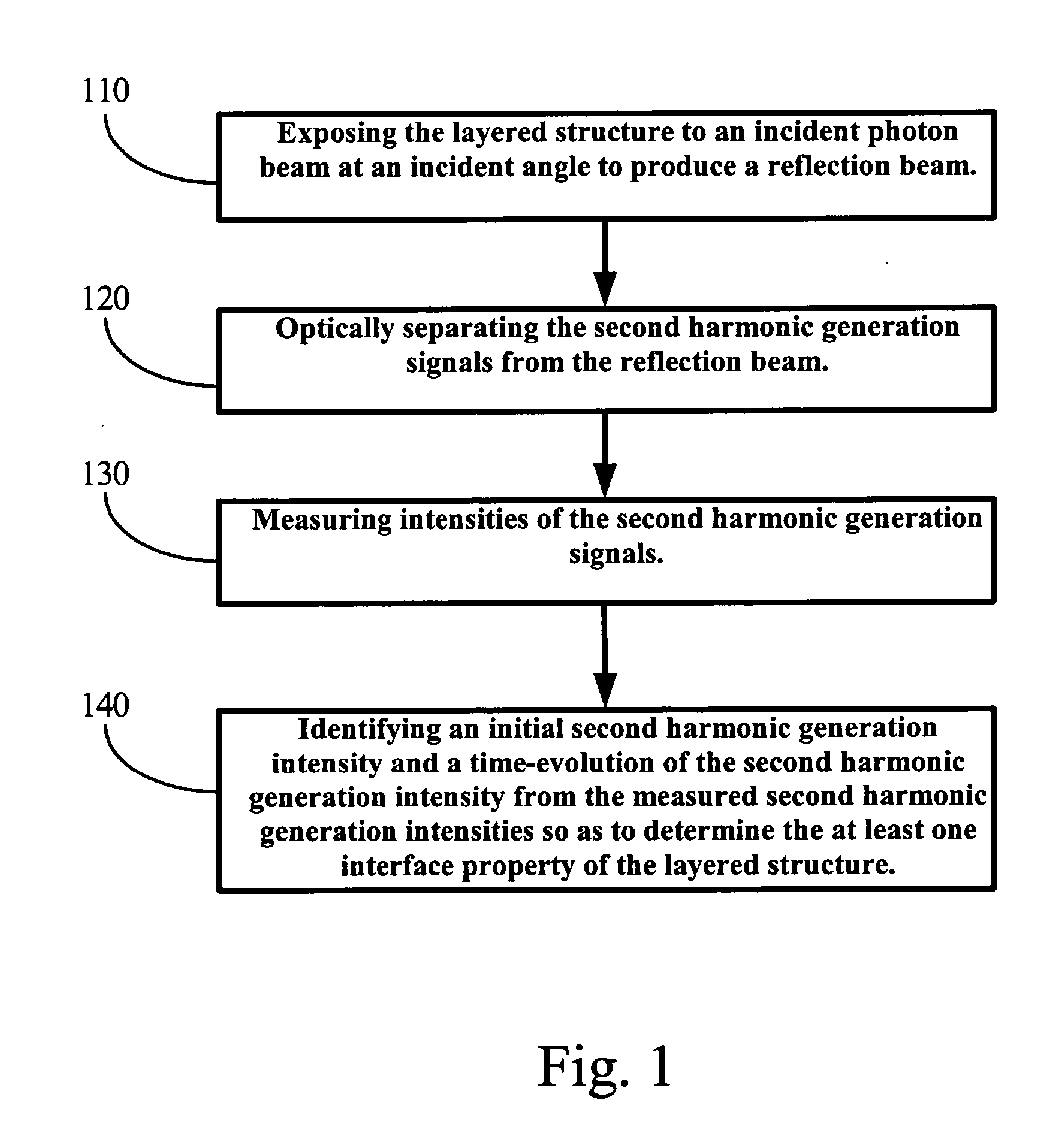
A method for non-invasively probing at least one interface property in a layered structure having at least one interface. In one embodiment, the method includes the steps of exposing the layered structure to an incident photon beam at an incident angle to produce a reflection beam, measuring intensities of the second harmonic generation signals from the reflection beam, and identifying an initial second harmonic generation intensity and a time evolution of second harmonic generation intensity from the measured second harmonic generation intensities so as to determine the at least one interface property of the layered structure.

Description

CROSS-REFERENCE TO RELATED PATENT APPLICATION [0001] This application is a continuation-in-part of U.S. patent application Ser. No. 10 / 363,347, filed Sep. 15, 2003, entitled “CONTACTLESS OPTICAL PROBE FOR USE IN SEMICONDUCTOR PROCESSING METROLOGY,” by Norman H. Tolk, Gunter Luepke, and Wei Wang, the disclosure for which is hereby incorporated herein by reference in its entirety, which status is allowed and itself claims the benefit, pursuant to 35 U.S.C. §119(e), of provisional U.S. patent application Ser. No. 60 / 125,002, filed Mar. 18, 1999, entitled “CONTACTLESS OPTICAL PROBE FOR USE IN SEMICONDUCTOR PROCESSING METROLOGY,” by Norman H. Tolk, Gunter Luepke, and Wei Wang, which is incorporated herein by reference in its entirety. This application also is a continuation-in-part of U.S. patent application Ser. No. 10 / 976,358, filed Oct. 28, 2004, entitled “APPARATUS AND METHODS OF USING ULTRA FAST SPIN DYNAMICS IN SEMICONDUCTOR HETEROSTRUCTURES PROBED BY SECOND HARMONIC GENERATION” by...

Claims


Application Information

Patent Timeline
Patent Type & Authority Applications(United States)
IPC IPC(8): G02F2/02
CPCG01N21/63G01N21/55
Inventor ALLES, MICHAEL LEETOLK, NORMAN H.JUN, BONGIMPASTERNAK, ROBERTSCHRIMPF, RONCRISTOLOVEANU, SORIN
Owner VANDERBILT UNIV
Why Eureka
Try Eureka