

Wireless communication system
a communication system and wireless technology, applied in the field of wireless communication systems, can solve the problems of cumbersome installation and maintenance of ap in conventional wireless lan systems, and achieve the effect of highest communication efficiency in the area
- Summary
- Abstract
- Description
- Claims
- Application Information
AI Technical Summary
Benefits of technology
Problems solved by technology
Method used
Image

Examples
embodiment 1
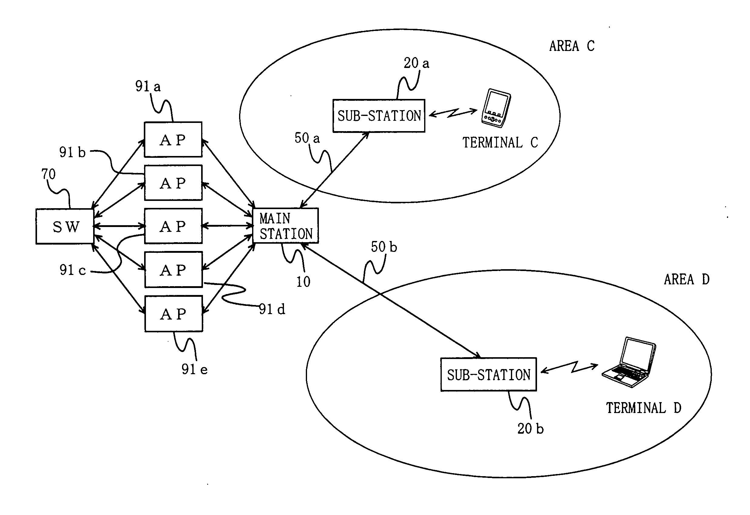
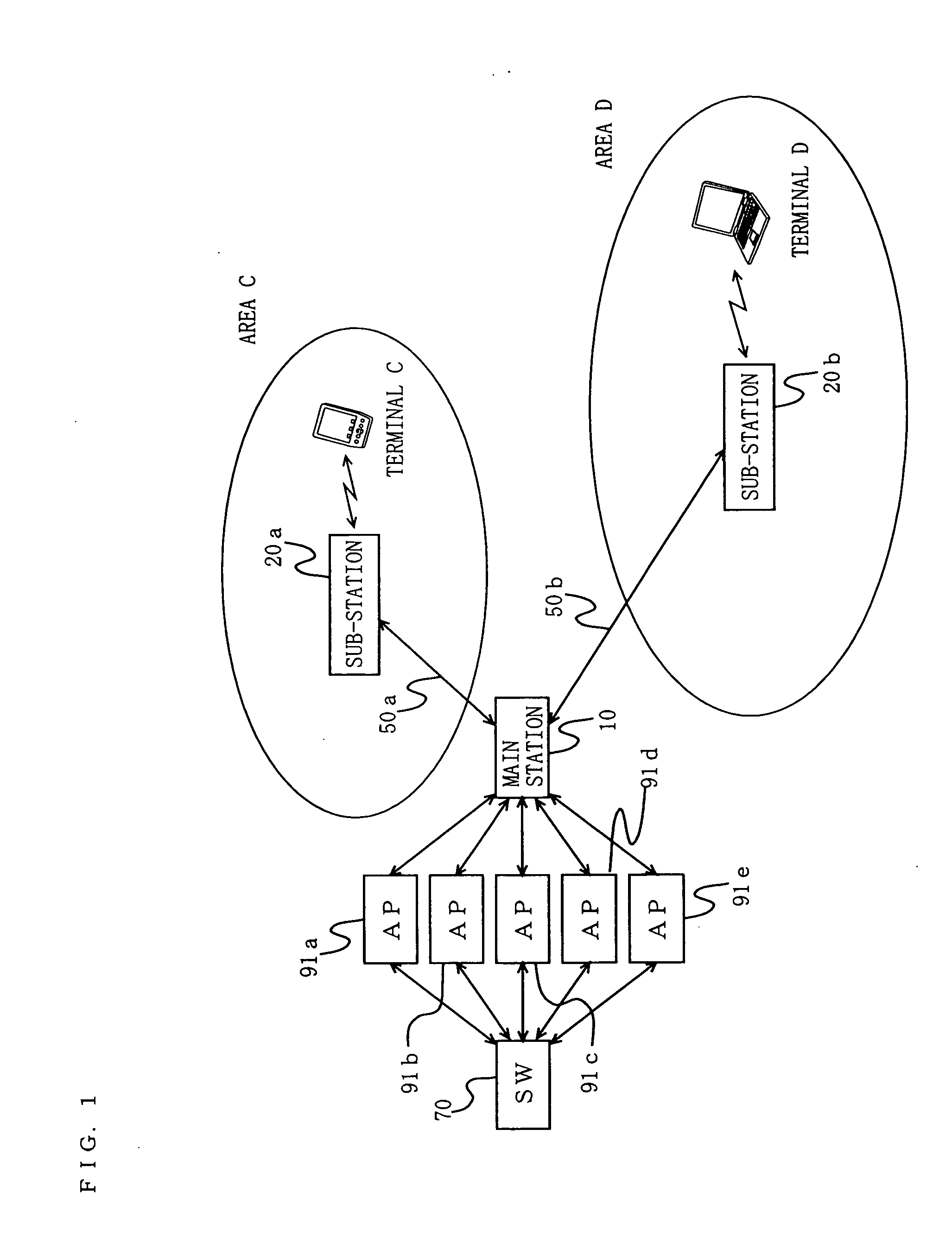
[0166] Hereinafter, an entire structure of a wireless communication system according to Embodiment 1 of the present invention will be described with reference to the accompanying drawings. FIG. 1 is a block diagram showing the entire configuration of the wireless communication system.
[0167] The wireless communication system of Embodiment 1 has areas C and D (in the claims, the areas C and D are each referred to as a wireless communication area, and collectively referred to as a local area), and comprises a main station 10, sub-stations 20a and 20b, optical fiber transmission paths 50a and 50b, a network switch (abbreviated as SW in FIG. 1) 70, access points (abbreviated as AP in FIG. 1) 91a to 90e, and terminals C and D. Note that the terminals C and D are representative terminals which are present in the respective areas. Therefore, a number of terminals are present in the actual areas C and D in addition to the terminals C and D.
[0168] The area C is an area in which the sub-stat...
embodiment 2
[0270] Hereinafter, an entire configuration of a wireless communication system according to Embodiment 2 of the present invention will be described with reference to the drawings. Note that the entire configuration of the wireless communication system of Embodiment 2 is similar to that of Embodiment 1, and therefore, FIG. 1 is referenced.
[0271] The SW 70 and the APs 91a to 91e are similar to those of Embodiment 1 and will not be explained. Also, the sub-stations 20a and 20b are similar to those of Embodiment 1, and therefore, FIG. 3 is referenced.
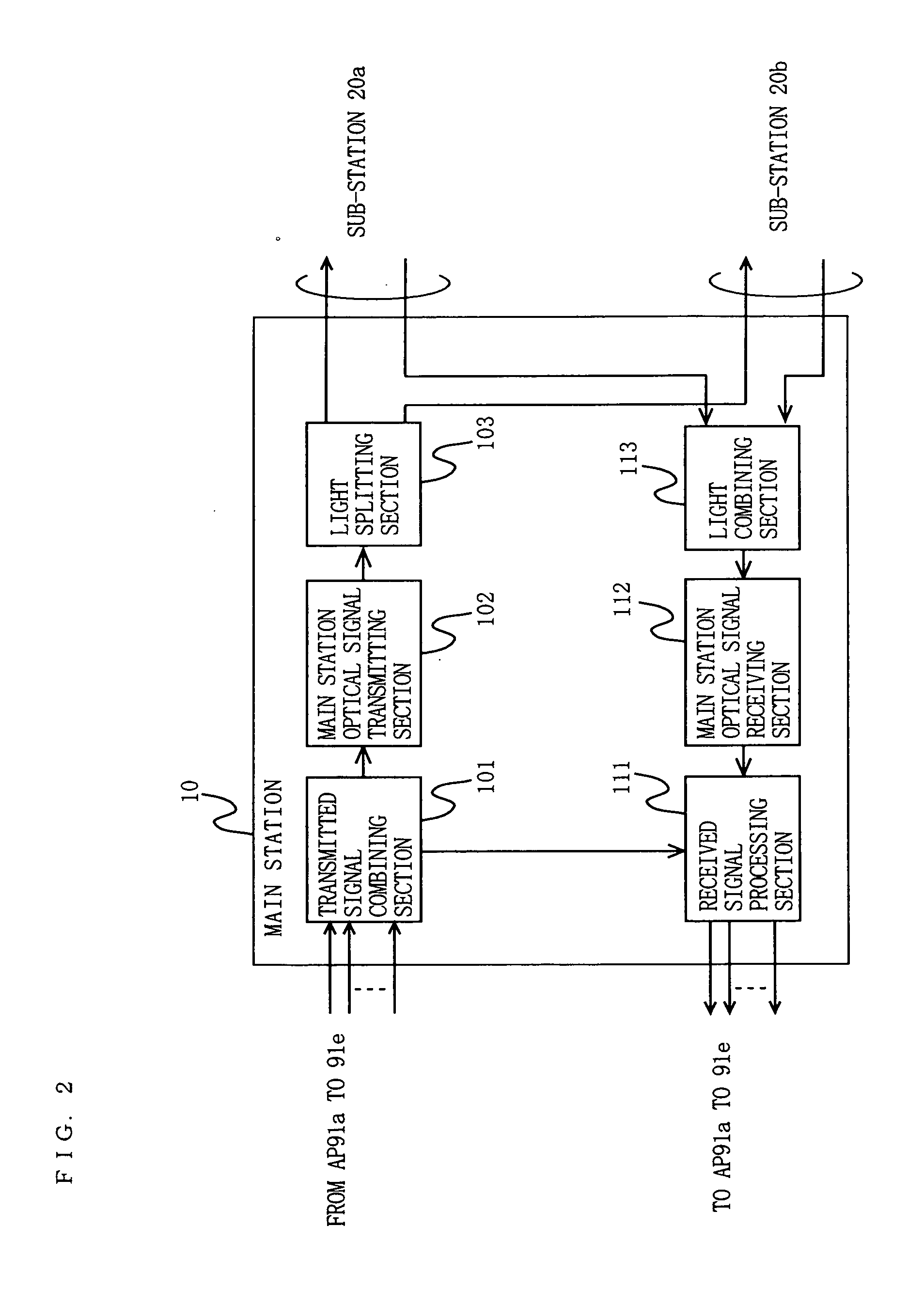
[0272] Here, a main station 10 of the wireless communication system of Embodiment 2 will be described. The main station 10 of Embodiment 2 converts an electrical signal type wireless LAN signal input from the APs 91a to 91e to an optical signal, and selectively outputs the optical signal to each of the sub-stations 20a and 20b. More specifically, the main station 10 outputs the optical signal to both or one of the sub-station 20a and the ...
embodiment 3
[0325] Hereinafter, an entire configuration of a wireless communication system according to Embodiment 3 of the present invention will be described with reference to the drawings. FIG. 17 is a block diagram showing the entire configuration of the wireless communication system of Embodiment 3. The wireless communication system of Embodiment 3 is different from that of Embodiment 1 in that an area G is also present in a main station 30. The other elements are similar to those of Embodiment 1 and will not be explained.
[0326] A SW 70 and APs 91a to 91e of Embodiment 3 are similar to those of Embodiment 1 and will not be explained. The configuration of sub-stations 20a and 20b of Embodiment 3 is similar to that of Embodiment 1 of FIG. 3 and will not be explained.
[0327] Here, the main station 30 of Embodiment 3 will be described with reference to the drawings. FIG. 18 is a block diagram showing a configuration of the main station 30 of Embodiment 3. The main station 30 is the same as th...
PUM
 Abstract
Description
Claims
Application Information