
Broadband fiber optic tap

a fiber optic tap and wideband technology, applied in the field of optical fiber taps, can solve the problems of reducing efficiency and suffering from inherent wavelength dependence, and achieve the effects of reducing the relative amount of light, reducing the wavelength dependence of the tap, and extending the wavelength rang

Active Publication Date: 2006-03-02
NEOPHOTONICS CORP
View PDF8 Cites 11 Cited by
  • Summary
  • Abstract
  • Description
  • Claims
  • Application Information

AI Technical Summary

Benefits of technology

[0011] Advantageously, the present invention provides an optical tap that is relatively insensitive to wavelength and thus allows operation over a relatively broad wavelength range.
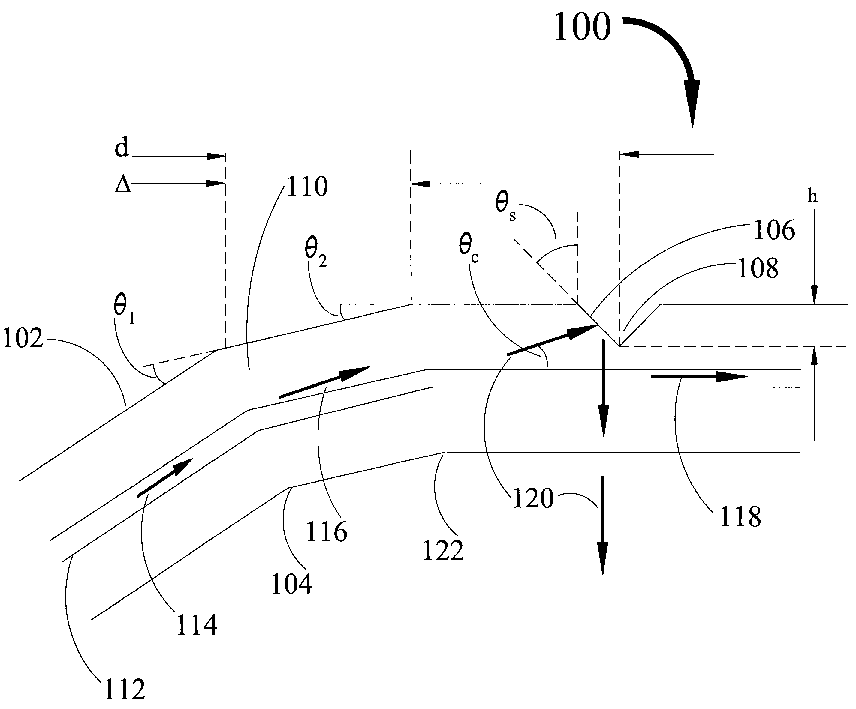
[0012] In accordance with the present inventive teachings, the present invention accomplishes this through a single-mode fiber with two annealed microbends formed in the fiber, using, e.g., CO2 laser radiation, and a reflecting surface formed in the cladding downstream of the two microbends. The reflecting surface is formed using the same CO2 laser used to form the microbends by using laser ablation to create a notch in the cladding of the fiber. The notch is formed in the cladding of the fiber so as to create a reflecting surface at an angle of approximately 44 degrees to the perpendicular of the fiber axis, thus inducing total internal reflection for light incident on the surface. The two microbends are spaced apart by a distance approximately equal to one-half of the intermodal beat length for the LP01 and LP11 modes so as to cause anti-resonant coupling. Anti-resonant coupling reduces the relative amount of light in the LP11 mode while populating higher-order modes that are coupled out more efficiently, thus greatly reducing the wavelength dependence of the tap and hence greatly expanding its wavelength range.

Problems solved by technology

While this technique offers many desirable features, such as small size, low insertion loss, and ease of manufacture, it suffers from inherent wavelength dependence owing to the guiding properties of the fiber.
Efficiency is reduced when light is scattered out of a fiber core but fails to exit the fiber at the tap and instead is lost at points downstream of the tap.
Unfortunately, in optical taps made in conventional telecommunications fiber according to the teachings of the '398 application, the tap efficiency may vary by as much as 400% over the wavelength band from 1310 nm to 1550 nm.

Method used


Image

  • Broadband fiber optic tap
  • Broadband fiber optic tap
  • Broadband fiber optic tap

Examples


Embodiment Construction

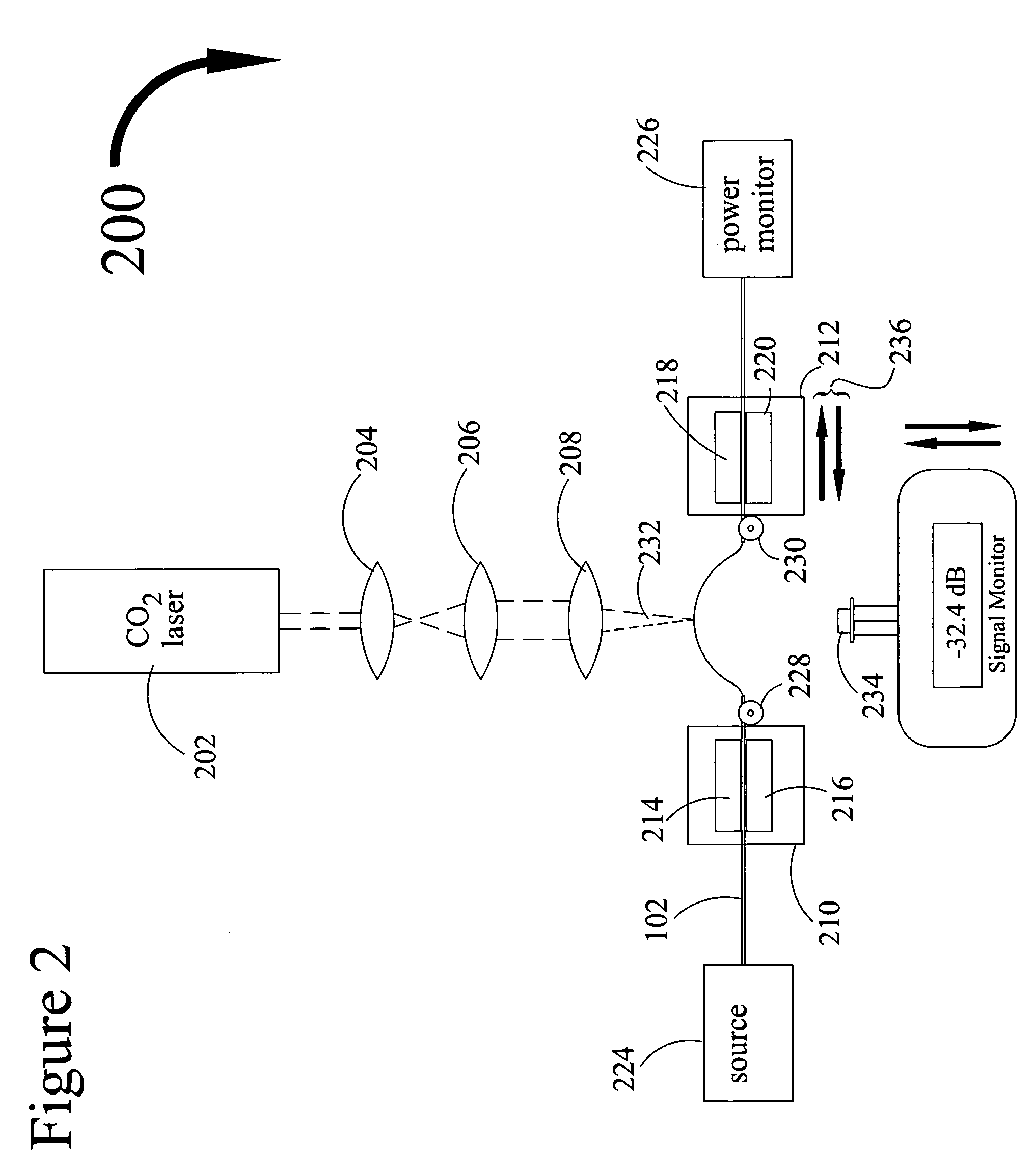
[0028] Referring to the drawings, FIG. 1 depicts fiber optic tap 100 comprising optical fiber 102, primary microbend 104, secondary microbend 122 and reflecting surface 106. Reflecting surface 106 and microbends 104 and 122 are formed using radiation from a single CO2 laser as described below. Hereinafter a microbend refers to a bent section of fiber having a radius of curvature comparable to the diameter of the fiber. In contrast, a macrobend refers to a bend having a radius of curvature that is relatively large compared to the diameter of the fiber. In the preferred embodiment, microbends 104 and 122 are annealed microbends, meaning they are formed in the fiber by locally heating the fiber above its softening temperature. Microbends 104 and 122 are thus permanent, stress-free structures in the fiber.

[0029] As described in more detail below, microbends 104 and 122 serve to scatter optical energy out of a core of fiber 102 into its cladding. The scattered energy is reflected out of...


PUM

PropertyMeasurementUnit
angleaaaaaaaaaa
wavelength bandaaaaaaaaaa
wavelengthaaaaaaaaaa

Abstract

A broadband optical fiber tap for transferring optical energy out of an optical fiber having an optical fiber with a primary and secondary microbends for the purpose of coupling optical energy into the higher-order modes of the fiber, and a reflecting surface formed in the cladding of the fiber and positioned at an angle so as to reflect, by total internal reflection, higher-order mode energy away from the optical fiber. In the preferred embodiment, the two microbends are spaced apart by a distance approximately equal to one-half of the intermodal beat length for LP01 and LP11 modes of a single-mode fiber.

Description

CLAIM TO PRIORITY [0001] This application claims priority of co-pending U.S. provisional application entitled “Broadband Fiber Optic Tap”, filed Aug. 31, 2004 and accorded Ser. No. 60 / 606,002; which is incorporated by reference herein.BACKGROUND OF THE INVENTION [0002] 1. Field of the Invention [0003] This invention relates to a component for coupling optical energy out of an optical fiber, and particularly to an optical fiber tap that efficiently couples optical energy out over a relatively broad wavelength range. [0004] 2. Description of the Prior Art [0005] The ever-increasing complexity of fiber optic networks has created a need for devices that can measure the optical energy flowing through an optical fiber. Such devices are useful for network monitoring and control purposes, in many ways analogous to water gauges used to monitor the flow of water through pipes. [0006] In order to measure the flow of optical energy in an optical fiber, a small fraction of the optical energy mus...

Claims


Application Information

Patent Timeline
Patent Type & Authority Applications(United States)
IPC IPC(8): G02B6/26
CPCG02B6/2852
Inventor POOLE, CRAIG
Owner NEOPHOTONICS CORP
Learn More