[0021] The inventors have recognized that a
wafer processing system does not need four (or more load ports. Instead, by providing additional storage and the ability to drop off FOUPs to a tool or pick them up from the tool while additional FOUPs are being processed tool efficiency can be enhanced.
[0022] According to an embodiment of the present invention, a load port design allows a new FOUP to be lowed to the load-port prior to the completed FOUP being removed. This localized buffering or swapping can be accomplished with a variety of motions including but not limited to linear (e.g., horizontal or vertical) motion or rotational motion. The load port includes a quick swap buffer (QSB) that can be optimized for compatibility with both unidirectional and bi-directional systems. The QSB allows on OHT car to rapidly swap a finished FOUP with a new FOUP on a tool. With this approach, the AMHS would be signaled that the drop-off location is available as soon as the tool has completed processing, or when the load port has moved the FOUP to the local storage. This allows the same car to drop off a new FOUP and then immediately (or almost immediately) retrieve the completed one. This can drastically reduce or even eliminate the wait time for the tool. In addition, the loading of the OHT can be significantly reduced for both motion and scheduling, thus reducing traffic in the FAB.
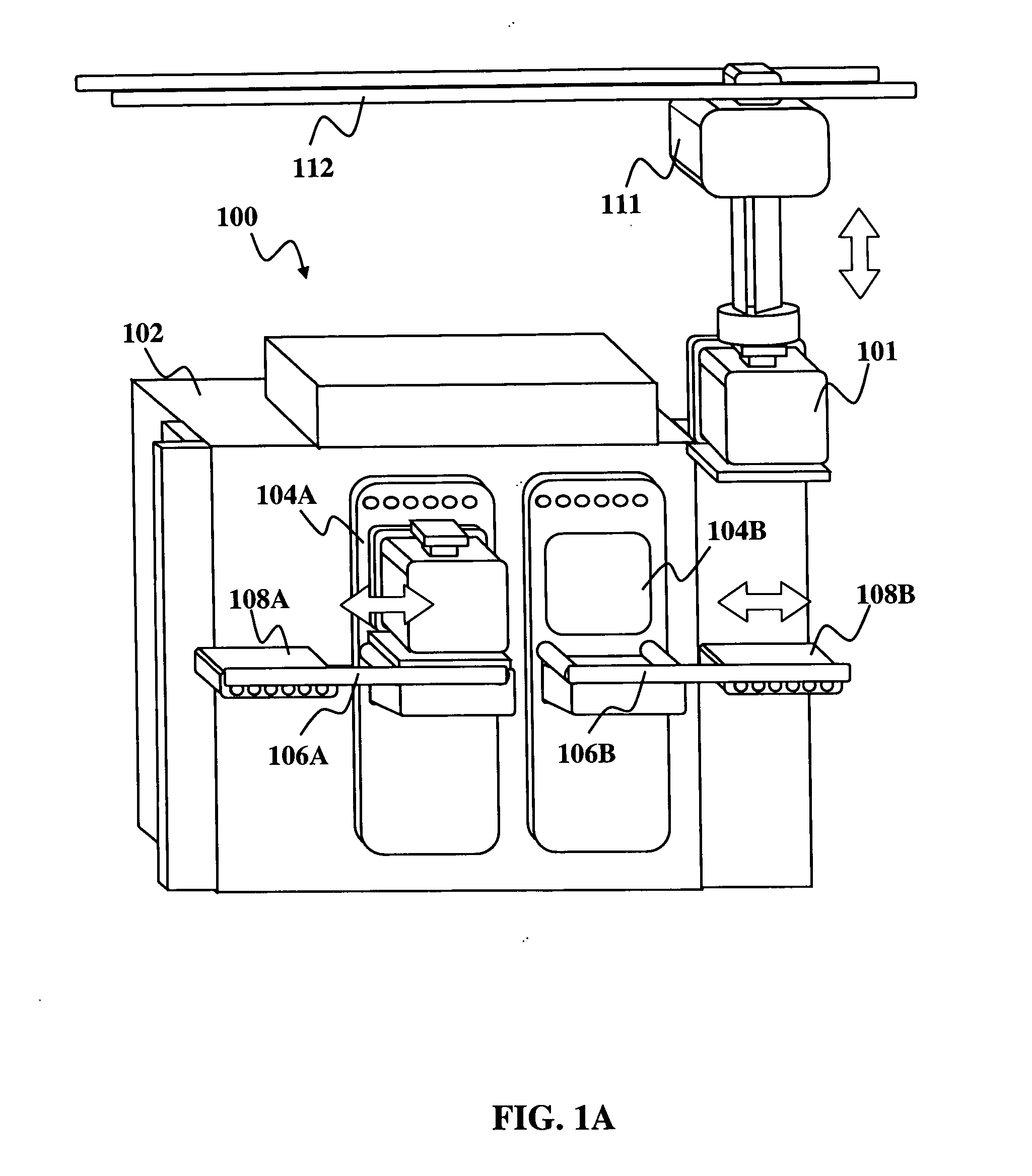
[0025] The buffers 106A, 106B reduce the load on the materials
handling system by providing both local storage and the ability to move the pods 101 between the load ports 104A, 104B and local storage at the storage locations 108A, 108B. According to another embodiment of the invention, the apparatus 100 may be used to reduce the load on the automated material
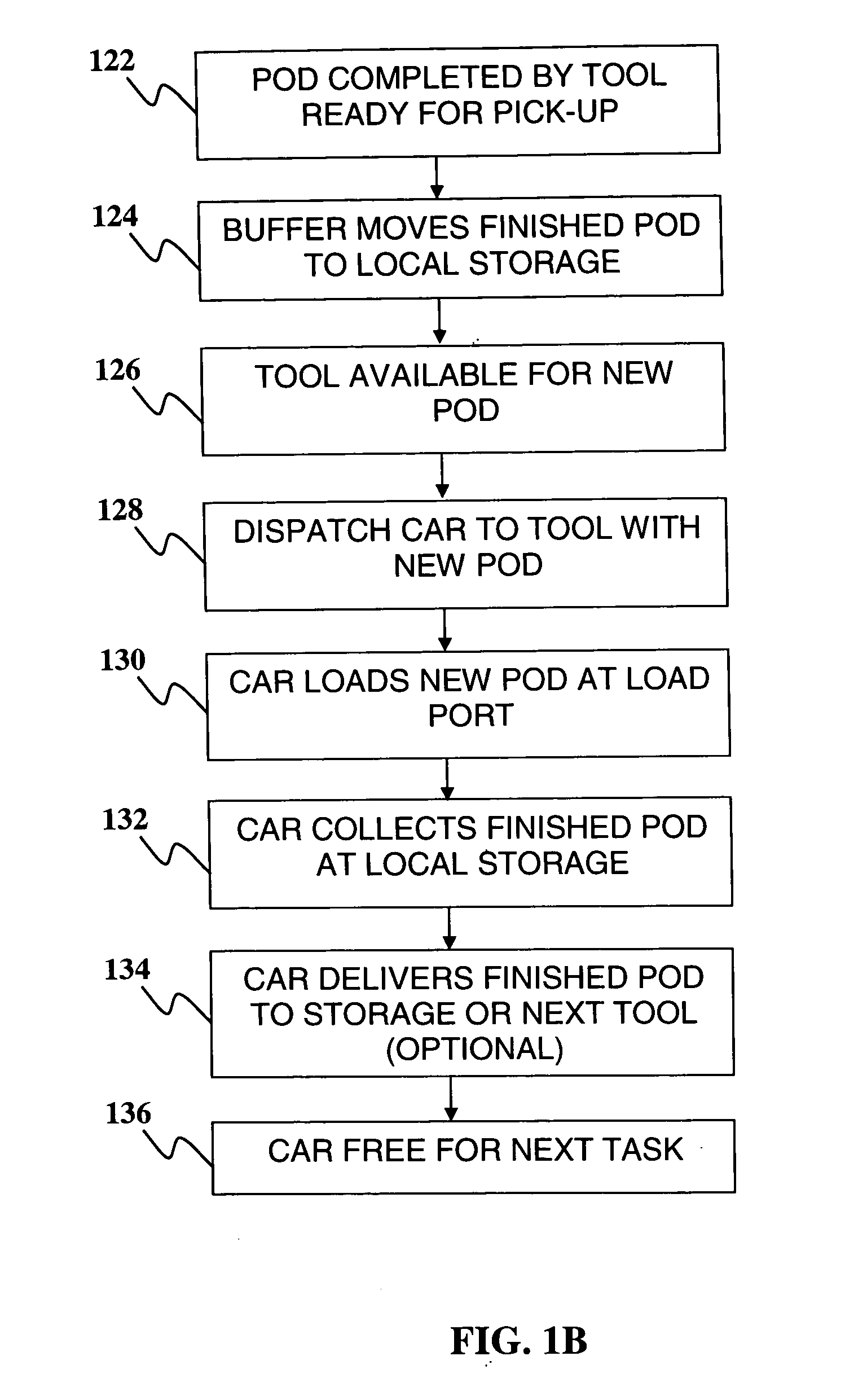
handling system having one or more cars for deliver materials pods to one or more
materials processing tools during processing of materials. The flow diagram shown in FIG. 1B illustrates an example of the steps of the method. The advantages of the apparatus of FIG. IA can be readily understood by simultaneously referring to FIG. 1A and the flow diagram of FIG. 1B.
[0027] Note that in a unidirectional materials handling system, if the storage location 108A is located down
stream of the load port 104A, the buffer 106A can move a finished pod 101 from the load port 104A to the storage location 108A. The car 111 can subsequently drop off a new pod at the load port 104A and then almost immediately afterwards pick up the finished pod 101 at the storage location 108A without having to change direction. On the other hand, if the storage location 108B may be located upstream of the load port 104B. When the tool 102 finishes processing a pod 101 the car 111 can drop off a new pod at the storage location 108B and then almost immediately afterwards pick up the finished pod at the load port 104B. The buffer 106B can then move the new pod to the load port 104B.
[0028] Even with bi-directional OHT cars, the buffers 106A, 106B can greatly reduce the load on the materials handling system since they can both locally store and move the pods 101. In a conventional local storage system, by contrast, the materials handling system must move the pods from the load ports to the local storage and vice versa.
[0037] According to another alternative embodiment, buffers may be configured to simultaneously swap a first pod and second pod between a storage location
proximate the front end of the tool and one of the load ports. This is particularly advantageous in reducing the burden on the materials handling system. For example, an OHT car can place a new pod at the tool before the tool finishes processing another pod. If the buffer can swap the pods between the load port and storage location, an OHT car can be available for other tasks as soon as it drops off a pod. Mechanisms of the types depicted in FIGS. 6-7 are particularly useful in this context. For example, FIG. 8 depicts a tool 802 having a load port 804 and a swap buffer 800 that includes a mechanism of the type depicted in FIG. 7, e.g., having carrier that rides on bearings along first and second offset tracks. The buffer mechanism 800 further includes a simple
horizontal translation mechanism 806. The first pod carrier can move a first pod 801A along the tracks while the translation mechanism 806 moves a second pod 801B underneath (or above) the first pod 801A. In this manner, the buffer mechanism can simultaneously (or nearly simultaneously) swap the first and second pods between the load port 804 and a storage location 808.

