Torsional coupling

a torsional coupling and coupling technology, applied in the direction of fluid couplings, couplings, mechanical equipment, etc., can solve the problems of premature engine failure, reduced gear life, excessive noise, etc., to increase the rotational speed of the body, and increase the effective stiffness of the torsional coupling

Inactive Publication Date: 2006-03-02
CATERPILLAR INC
View PDF73 Cites 9 Cited by
  • Summary
  • Abstract
  • Description
  • Claims
  • Application Information

AI Technical Summary

Benefits of technology

[0006] In one aspect, this disclosure is directed to a torsional coupling. The coupling includes a body having a circumference and defining a center axis. The body is rotatable about the center axis. The coupling also includes a ring including an inner diameter disposed about the circumference. The ring includes a ring contact surface having a first radius, and the ring is configured to rotate about the center axis. A coupling element is associated with the body and is configured to apply a centrifugal force radially outwardly from the circumference of the body when the body rotates. The coupling element includes a coupling element contact surface having a second radius, which is different than the first radius of the ring contact surface. The coupling element contact surface is in contact with the ring contact surface and is configured to apply a force against the ring contact surface to rotate the ring relative to the body and increase the effective stiffness of the torsional coupling as the rotational speed of the body increases.
[0007] In another aspect, this disclosure is directed to an engine including a cylinder block and a gear train. At least one gear of the gear train includes a body having a circumference and defining a center axis. The body is rotatable about the center axis. The gear also includes a ring having an inner diameter disposed about the circumference and having a ring contact surface having a first radius. The ring is also configured to rotate about the center axis. A coupling element is associated with the body and is configured to apply a centrifugal force radially outwardly from the circumference of the body when the body rotates. The coupling element includes a coupling element contact surface having a second radius which is different than the first radius of the ring contact surface. The coupling element contact surface is in contact with the ring contact surface and is configured to apply a force against the ring contact surface to rotate the ring relative to the body and increase the effective stiffness of the torsional coupling as the rotational speed of the body increases.

Problems solved by technology

Torsional vibrations resulting from engine harmonic excitation are common and lead to excessive noise and reduced gear life, which in turn, may cause premature engine failure.
However, the generally parallel plates disclosed in the '876 patent may not be positioned to readily resist wear from the coupling body that may occur as a result of manufacturing related misalignments.
This, in turn, may limit the life of the coupling and subsequently the engine system.

Method used


Image

  • Torsional coupling
  • Torsional coupling
  • Torsional coupling

Examples


Embodiment Construction

[0014] Reference will now be made in detail to exemplary embodiments that are illustrated in the accompanying drawings. Wherever possible, the same reference numbers will be used throughout the drawings to refer to the same or like parts.

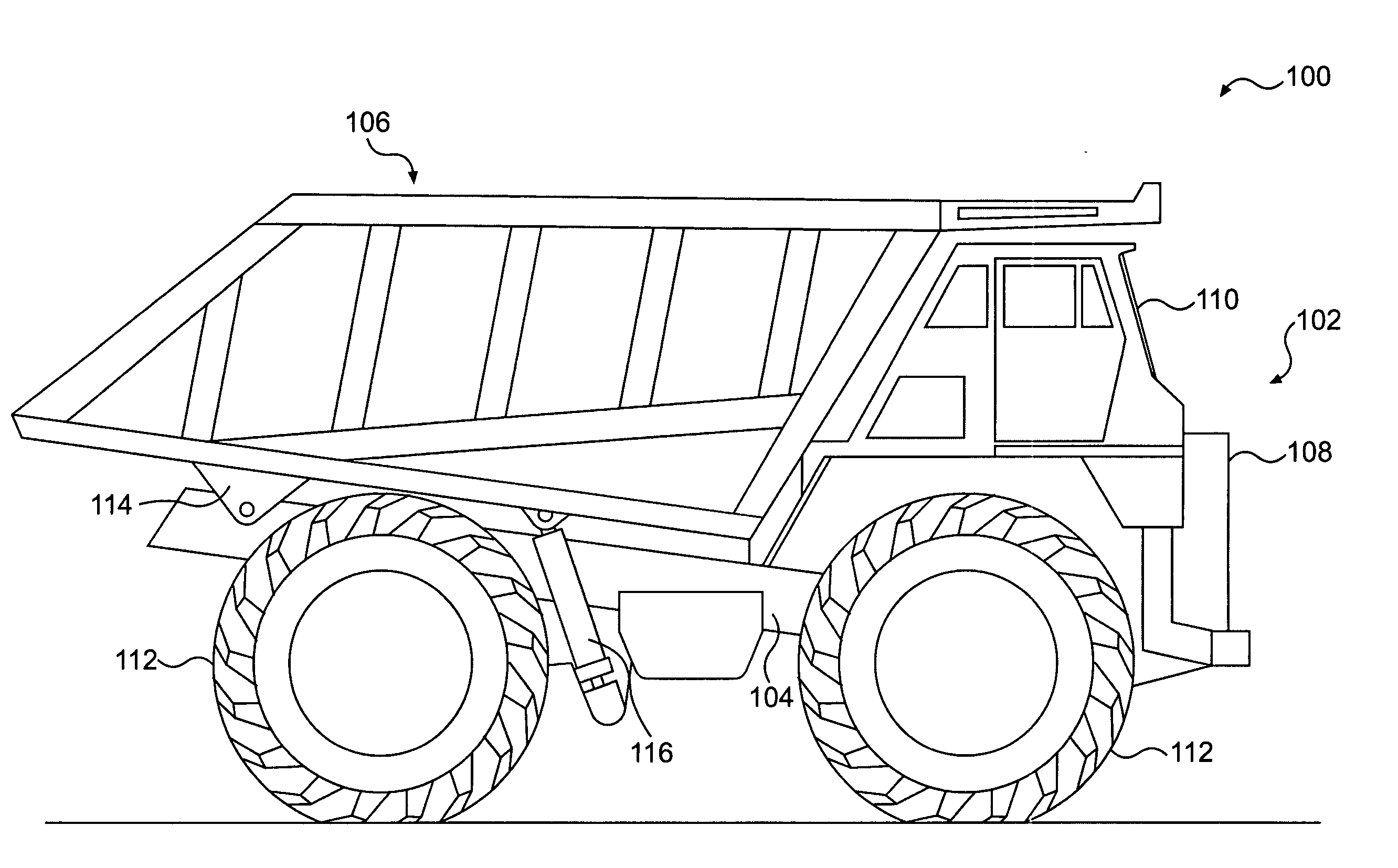
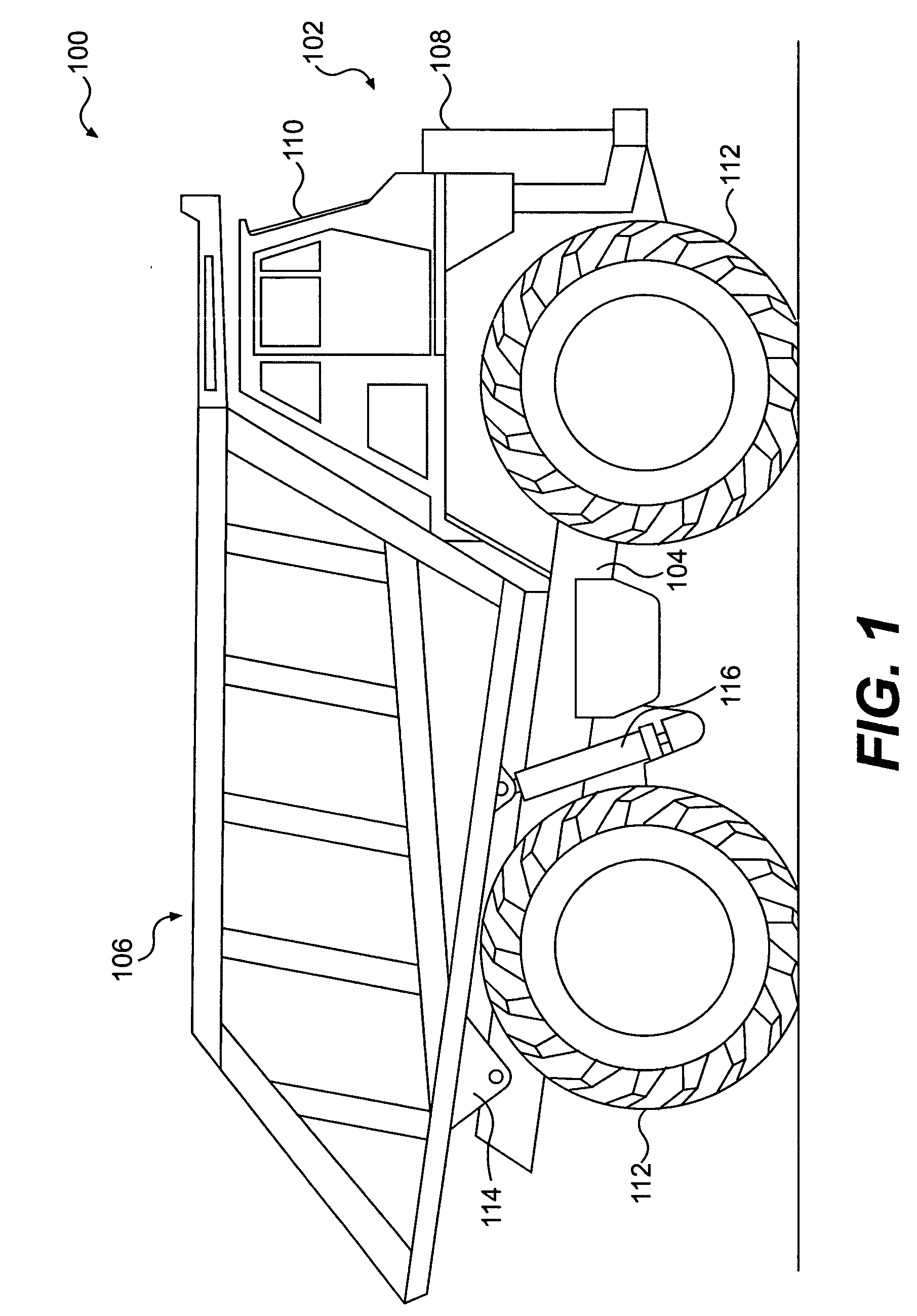
[0015] An exemplary embodiment of a work machine 100 is illustrated in FIG. 1. The exemplary work machine 100 includes a front end 102, a frame 104, and a payload container 106. The front end 102 may include an engine compartment 108 and an operator's cab 110. The engine compartment 108 may house an engine, a transmission, and / or other components used to power the work machine 100. The operator's cab 110 may include controls for operating and driving the work machine 100. The engine in the engine compartment 108 may drive wheels 112 attached to the frame 104, in a manner known in the art.

[0016] The payload container 106 may be connected to the frame 104 by a pivoting body support 114. The body support 114 may be located toward the rear end of the ...


PUM


Abstract

A torsional coupling includes a body having a circumference and defining a center axis. The body is rotatable about the center axis. The coupling also includes a ring including an inner diameter disposed about the circumference. The ring includes a ring contact surface having a first radius and the ring is configured to rotate about the center axis. A coupling element is associated with the body and is configured to apply a centrifugal force radially outwardly from the circumference of the body when the body rotates. The coupling element includes a coupling element contact surface having a second radius which is different than the first radius of the ring contact surface. The coupling element contact surface is in contact with the ring contact surface and is configured to apply a force against the ring contact surface to rotate the ring relative to the body and increase the effective stiffness of the torsional coupling as the rotational speed of the body increases.

Description

TECHNICAL FIELD [0001] This disclosure is directed to a torsional coupling. More particularly, this disclosure is directed to an engine having a torsional coupling. BACKGROUND [0002] Torsional vibrations resulting from engine harmonic excitation are common and lead to excessive noise and reduced gear life, which in turn, may cause premature engine failure. The harmonic excitation is produced by various torques applied to components within the engine, such as a crankshaft or cam shaft, during normal operation. For example, a torque applied to the crankshaft is constantly varied from a high torque, such as when a piston drives the crankshaft down and a low torque, such as when the crankshaft drives the piston upward in a cylinder block. The wide range of torques applied to the crankshaft induce harmonic excitation and torsional vibration in the engine. [0003] Some systems for reducing torsional vibration include inertial masses that, due to centrifugal force, would generally circle th...

Claims


Application Information

Patent Timeline
Patent Type & Authority Applications(United States)
IPC IPC(8): F16D3/12
CPCF16D31/02F16D3/80
Inventor BROSOWSKE, THOMAS ALAN
Owner CATERPILLAR INC
Why Eureka
Try Eureka