Suspension control system

Inactive Publication Date: 2006-03-02
HONDA MOTOR CO LTD
View PDF3 Cites 31 Cited by
  • Summary
  • Abstract
  • Description
  • Claims
  • Application Information

AI Technical Summary

Benefits of technology

[0009] The present invention has been achieved in view of the above-mentioned circumstances, and, according to one aspect of the invention, improves riding comfort by

Problems solved by technology

As such, the control response is delayed, which results in a deterioration of riding comfort during control of the rolling angle.
Accordingly, the damping force of the

Method used


Image

  • Suspension control system
  • Suspension control system
  • Suspension control system

Examples


first embodiment

[0041] the present invention will be described below with reference to FIGS. 1 to 9.

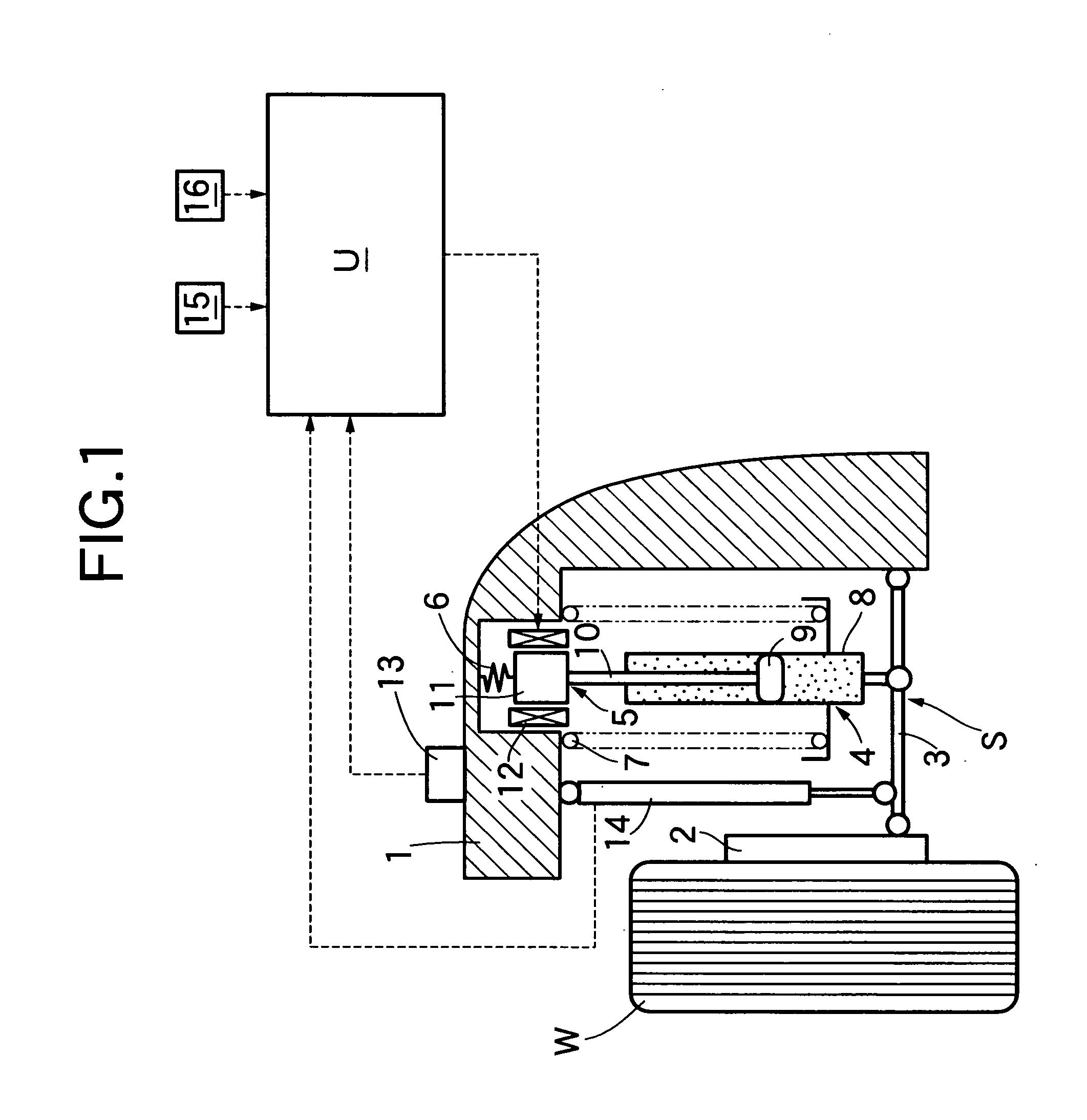
[0042] As shown in FIG. 1, a suspension S, which suspends a wheel W of a four-wheel automobile, includes a suspension arm 3 vertically supporting a knuckle 2 in a movable manner on a vehicle body 1; a damper 4 disposed in series to connect the suspension arm 3 and the vehicle body 1; and a coil spring 7 connecting an actuator 5 and a damper mount rubber 6 to the suspension arm 3 and the vehicle body 1. The damper 4 includes a cylinder 8 having a lower end supported on the suspension arm 3; a piston 9 slidably fitted within the cylinder 8; and a piston rod 10 extending upward from the piston 9. The actuator 5 includes a core 11 connecting the upper end of the piston rod 10 to the lower end of the damper mount rubber 6; and a coil 12 disposed to surround the circumference of the core 11. The damper 4 is of a known hydraulic type wherein, when the piston 9 moves within the cylinder 8 filled with oil, a ...


PUM


Abstract

In a suspension control system, accelerations detected by acceleration sensors are differentiated by a differentiator to calculate acceleration derivative values. Based on these values, a target electrical current calculating section calculates a target electrical current that is supplied to an actuator which controls a damping force of a damper. Before a rolling or pitch angle occurs in the vehicle, the change of the rolling or pitch angle is predicted to control the damping force of the damper, thereby improving the response of rolling angle and pitch angle control to achieve, simultaneously, an accurate posture control and a satisfactory riding comfort. Because the target electrical current calculating section corrects the target electrical current of the actuator based on a damper speed obtained by differentiating a damper displacement, even when a large input is applied to the damper due to an unevenness of the road surface, a proper posture control is performed.

Description

RELATED APPLICATION DATA [0001] The present invention is based upon Japanese priority application Nos. 2004-230206 and 2004-230207, which are hereby incorporated in their entirety herein by reference. BACKGROUND OF THE INVENTION [0002] 1. Field of the Invention [0003] The present invention relates to a suspension control system for a suspension which suspends a wheel of a vehicle, wherein the suspension includes a damper having an actuator for changing a damping force of the damper. [0004] 2. Description of the Related Art [0005] Japanese Patent Application Laid-open No. 2002-211224 discloses a suspension control method wherein the spring rate of a coil spring used by a suspension is changed by an actuator-generated torque according to the steering angle speed of a steering wheel and the rolling angle of a vehicle. Accordingly, any increase in the rolling angle due to the vehicle turning is suppressed, thereby improving running stability. [0006] However, in the method described in J...

Claims


Application Information

Patent Timeline
IPC IPC(8): B60G17/018
CPCB60G17/0182B60G2800/162B60G17/01908B60G17/08B60G2202/25B60G2400/0511B60G2400/0512B60G2400/0521B60G2400/0522B60G2400/104B60G2400/106B60G2400/202B60G2400/252B60G2400/60B60G2400/821B60G2500/104B60G2800/012B60G2800/014B60G17/019
Inventor IZAWA, MASAKIKATO, TAKAFUMISEKIYA, SHIGENOBUONOE, YOSHIOFUKUZATO, TSUKASA
Owner HONDA MOTOR CO LTD
Why Eureka
Try Eureka