Check patentability & draft patents in minutes with Patsnap Eureka AI!

Predictive engine combustion management

a technology of engine combustion management and engine control, applied in the direction of electrical control, process and machine control, instruments, etc., can solve the problems of engine operator not having sufficient skill to properly modify a map, engine damage to the engine, and conditions that do not match the conditions

Inactive Publication Date: 2006-03-02
OPTIMUM POWER TECH LP
View PDF11 Cites 37 Cited by
  • Summary
  • Abstract
  • Description
  • Claims
  • Application Information

AI Technical Summary

Benefits of technology

[0017] Those embodiments and the other embodiments discussed herein may furthermore be implemented in an engine, a cylinder, an engine control unit or engine control system controlling such an engine or cylinder, or a computer readable medium that may be executed by a processor to control such an engine or cylinder.
[0018] Accordingly, the present invention provides solutions to the shortcomings of prior engine control systems, apparatuses, and methods. Those of ordinary skill in the art will readily appreciate, therefore, that those and other details, features, and advantages of the present invention will become further apparent in the following detailed description of the preferred embodiments of the invention.

Problems solved by technology

The manufacturers may further prevent engine operators from modifying the maps for a variety of reasons, such as the manufacturers believe that their maps provide the best engine performance, the manufacturers are concerned that an engine operator might damage the engine by specifying inappropriate control values, or the manufacturers assume that an engine operator might not have sufficient skill to properly modify a map.
In certain cases, however, it is believed that those conditions do not match the conditions in which the engine is operated.
Consequently, stock maps sometimes limit, rather than optimize, an engine's performance.
Thus, map values may not be appropriate for an engine operating in transition such as, for example, an accelerating or decelerating engine.
It is also frequently a time consuming, difficult, and costly part of the calibration effort.
As will be recognized, when an engine is transitioning to a higher or lower speed or load or otherwise changing operating conditions during a current combustion cycle, the operational information from those previous engine cycles is likely not to be appropriate for a current engine cycle.

Method used


Image

  • Predictive engine combustion management
  • Predictive engine combustion management
  • Predictive engine combustion management

Examples


Embodiment Construction

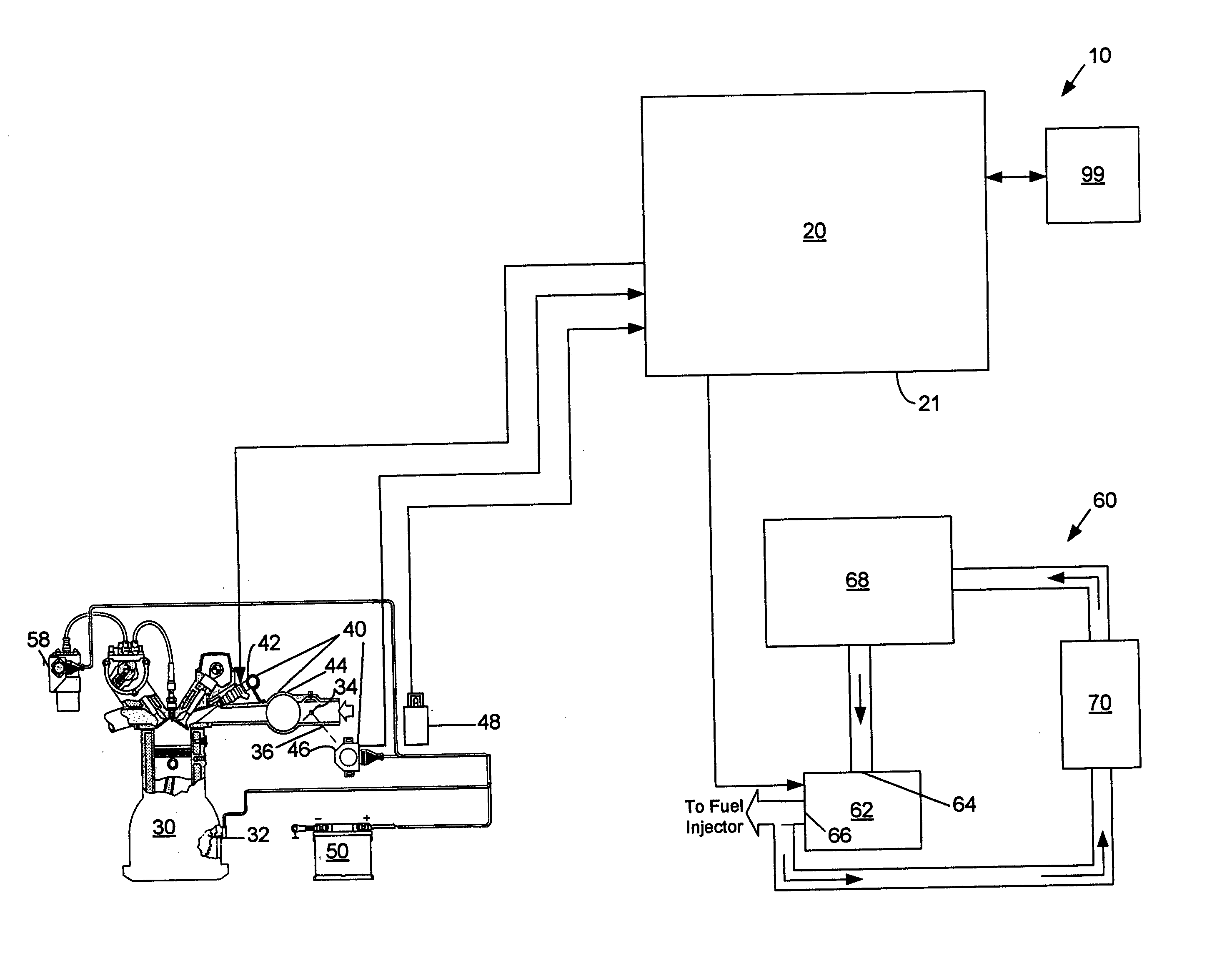
[0026] Reference will now be made to embodiments of predictive engine combustion management, examples of which are illustrated in the accompanying drawings. Details, features, and advantages of predictive engine combustion management will become further apparent in the following detailed description of embodiments thereof. It is to be understood that the Figures and descriptions included herein illustrate and describe elements that are of particular relevance to predictive engine combustion management, while eliminating, for purposes of clarity, other elements found in typical engines and engine control systems.

[0027] Systems, apparatuses, and methods to perform predictive engine combustion management are described herein. Aspects of those embodiments may also be included in processor based apparatuses, multi-processor based systems, and articles of manufacture that contain instructions which, when executed by a processor cause the processor to predictively manage engine combustion...


PUM


Abstract

A system, apparatus, and method for predicting an engine operating condition and providing a component in accordance with the prediction.

Description

CROSS-REFERENCE TO RELATED APPLICATIONS [0001] None. FIELD OF THE INVENTION [0002] The present invention is directed to an engine combustion management system for an internal combustion engine. In particular, this invention is directed to a system and method that predicts a future engine operating state and alters an operating parameter accordingly. BACKGROUND OF THE INVENTION [0003] It is generally accepted that the performance of an internal combustion engine is dependent on a number of factors that may include the operating cycle (e.g., two-stroke having 360 degrees of crankshaft rotation per cycle, four-stroke having 720 degrees of crankshaft rotation per cycle or Wankel rotary engines), the fuel type (e.g., gasoline, diesel, alcohol, liquid petroleum gas (LPG), or natural gas), the number and design of combustion chambers, the selection and control of ignition and fuel delivery systems, and the ambient conditions in which the engine operates. [0004] Examples of design choices f...

Claims


Application Information

Patent Timeline
IPC IPC(8): G06F17/00F02M51/00
CPCF02D11/105F02D37/02F02D41/0097F02D41/062F02D41/107F02M69/044F02D2041/1432F02D2041/1437F02D2200/0404F02D2200/1012F02D2250/21F02D41/2416
Inventor CHATFIELD, GLEN F.WELLS, DALE K.
Owner OPTIMUM POWER TECH LP
Features
  • R&D
  • Intellectual Property
  • Life Sciences
  • Materials
  • Tech Scout
  • Unparalleled Data Quality
  • Higher Quality Content
  • 60% Fewer Hallucinations
Learn More