Physical quantity sensor and method for manufacturing the same
- Summary
- Abstract
- Description
- Claims
- Application Information
AI Technical Summary
Benefits of technology
Problems solved by technology
Method used
Image

Examples
first embodiment
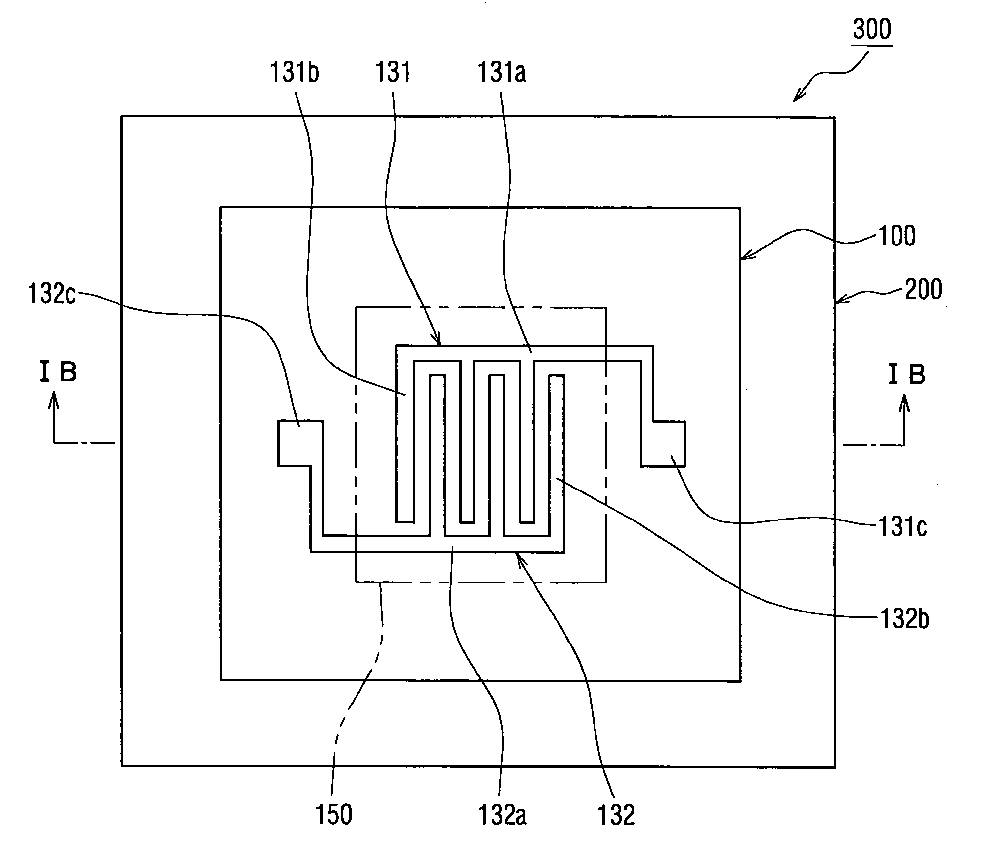
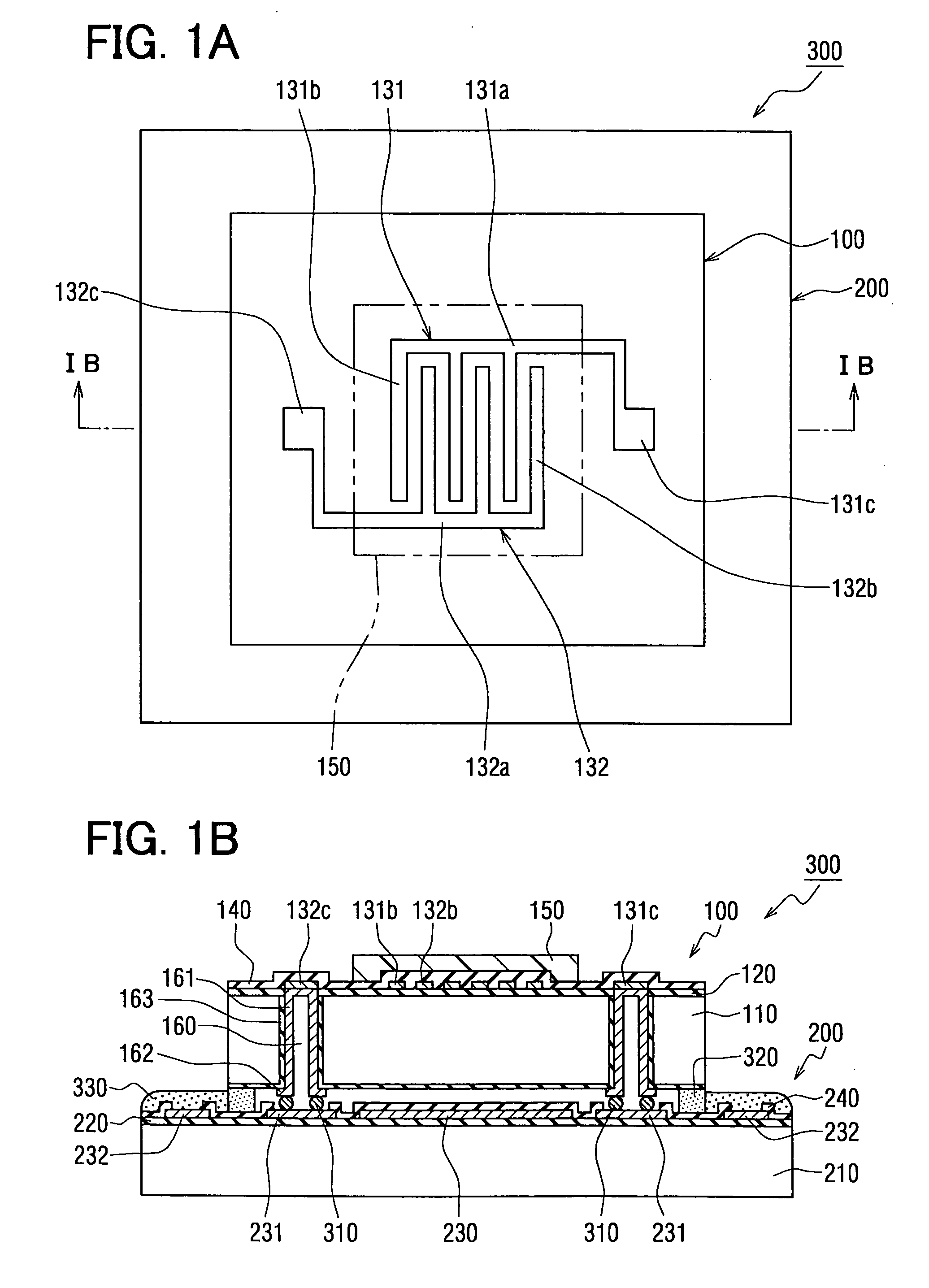
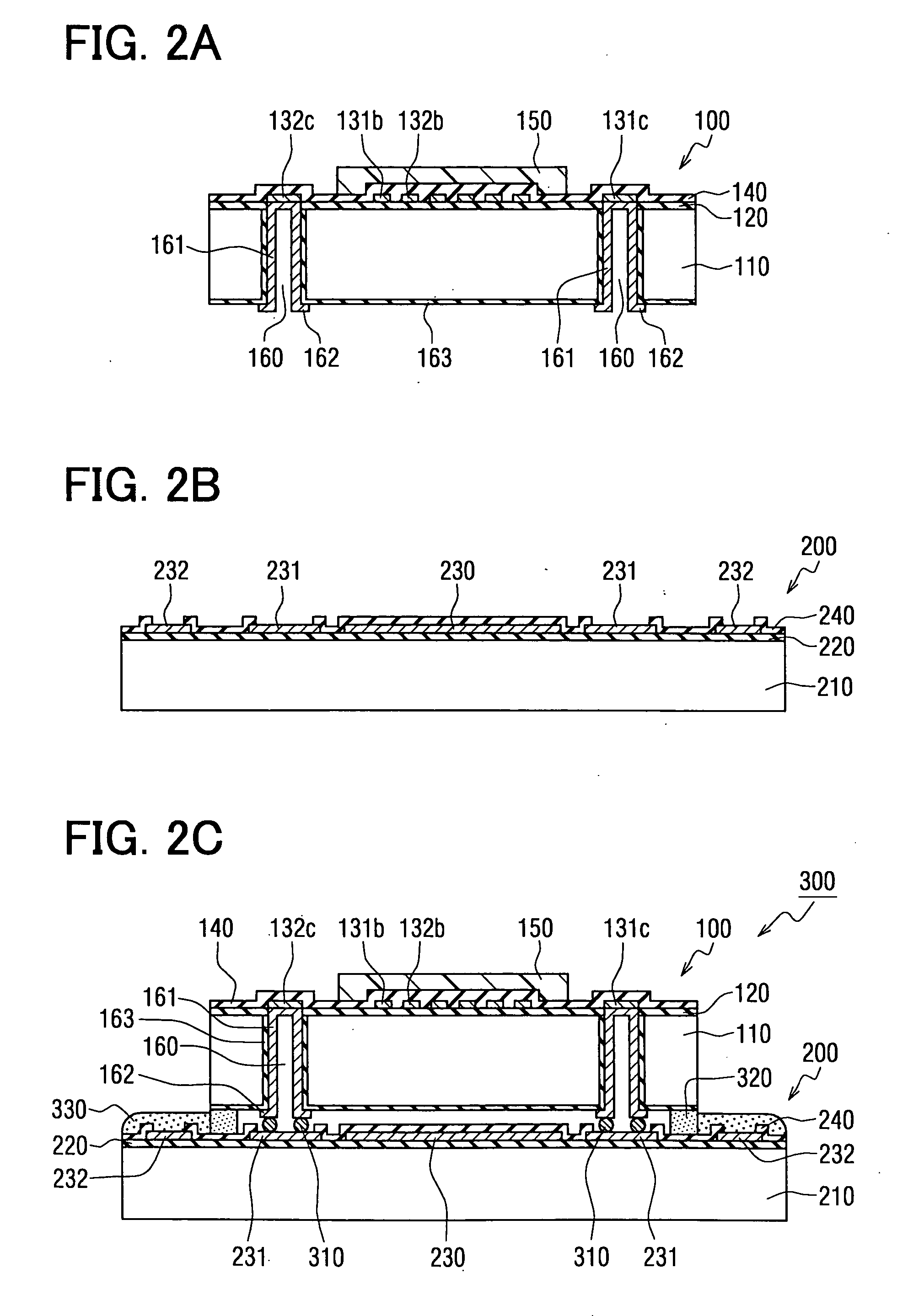
[0060]FIGS. 1A and 1B are a diagram for schematically showing a structure of a capacitance type humidity sensor 300 according to a first embodiment mode; FIG. 1A is a plan view for representing this capacitance type humidity sensor 300; and FIG. 1B is a sectional view for showing the humidity sensor, taken along a line IB-IB of FIG. 1A. It should be noted that for the sake of convenience, in FIG. 1A, one pair of electrodes located under both a humidity sensitive film and a second insulating film are illustrated in a transmission manner.
[0061] As indicated in FIG. 1A and FIG. 1B, the capacitance type humidity sensor 300 has been constituted by a detection board 100 and a circuit board 200. A detecting unit whose capacitance is changed in response to humidity has been provided on the side of one plane of the detection board 100. A circuit unit for processing a capacitance change of the detecting unit has been provided on the circuit board 200.
[0062] First, a description is made of t...
second embodiment
[0097] It should be understood that in the below-mentioned embodiment modes, a screen printing method according to the present invention is applied to forming of a humidity sensitive film of a capacitance type humidity sensor 400 which is manufactured by interposing a humidity sensitive film between one pair of electrodes, while a relative dielectric constant of the humidity sensitive film is changed in response to humidity.
[0098] A first description is made of a schematic structure of a capacitance type humidity sensor 400 with reference to FIGS. 4A snd 4B. FIG. 4A is a plan view for representing this capacitance type humidity sensor 400, and FIG. 4B is a sectional view for showing the humidity sensor 400, taken along a line IVB-IVB of FIG. 4A. It should be noted that for the sake of convenience, in FIG. 4A, one pair of electrodes located under both a humidity sensitive film and a second insulating film are illustrated in a transmission manner. Also, in FIG. 4A and FIG. 4B, only a...
third embodiment
[0130]FIGS. 10A and 10B are a diagram for schematically showing a structure of a capacitance type humidity sensor 500 according to a third embodiment mode; FIG. 10A is a plan view for representing this capacitance type humidity sensor 500; and FIG. 10B is a sectional view for showing the humidity sensor 500, taken along a line XB-XB of FIG. 10A. It should be noted that for the sake of convenience, in FIG. 10A, one pair of electrodes located under a humidity sensitive film are illustrated by a broken line.
[0131] In FIG. 10A and FIG. 10B, reference numeral 510 shows a substrate, to which a flexible substrate having flexibility has been applied in this embodiment mode. If materials own flexibility as a structural material of the substrate 510, then there is no specific limitation. Thus, in this embodiment mode, a thermoplasitic resin film made of a liquid crystal polymer (LCP) having a thickness of 25 μm has been applied to the structural material of the substrate 510.
[0132] Then, on...
PUM
| Property | Measurement | Unit |
|---|---|---|
| Length | aaaaa | aaaaa |
| Length | aaaaa | aaaaa |
| Length | aaaaa | aaaaa |
Abstract
Description
Claims
Application Information
 - Generate Ideas
- Intellectual Property
- Life Sciences
- Materials
- Tech Scout
- Unparalleled Data Quality
- Higher Quality Content
- 60% Fewer Hallucinations
Browse by: Latest US Patents, China's latest patents, Technical Efficacy Thesaurus, Application Domain, Technology Topic, Popular Technical Reports.
© 2025 PatSnap. All rights reserved.Legal|Privacy policy|Modern Slavery Act Transparency Statement|Sitemap|About US| Contact US: help@patsnap.com