Quiet vertical takeoff and landing aircraft using ducted, magnetic induction air-impeller rotors

Inactive Publication Date: 2006-03-09
SANDERS JR JOHN K +3
View PDF7 Cites 125 Cited by
  • Summary
  • Abstract
  • Description
  • Claims
  • Application Information

AI Technical Summary

Benefits of technology

[0009] The present invention solves the problems of the prior VTOL vehicles by providing a novel engine design for quiet, electrically-powered, and highly efficient flight performance. The engine has an air-impeller rotor formed with a plurality of blades with inner ends fixed to a hub and outer ends fixed to a disk or annular shaped outer ring arranged to float on magnetic bearings and driven by electric-powered magnetic induction elements arrayed on the impeller disk and complementarily on the duct housing. The duct housing serves a dual use of isolating the rotor for safety and deflecting or absorbing noise. The engine with air-impeller rotor is arranged vertically to provide thrust for vertical takeoff and landing. A pitch change mechanism is provided to vary the thrust by changing the pitch of the blades. An air vane assembly is used to deflect or direct a portion of the air thrust output of the rotor to provide a horizontal thrust component for horizontal translation and maneuvering. The magnetic induction air-impeller engine may employ dual, modular rotors in coaxial, contra-rotating configuration for increased thrust and gyroscopic stability.
[0010] The present invention is also directed to a new class of VTOL vehicles which use one or more of the magnetic induction air-impeller engines for VTOL flight in various military, commercial or recreational applications and with various flight speed and payload capacities. A single-engine vehicle has an annular shape and dual contra-rotating rotors in a central air flow channel adapted for unmanned surveill

Problems solved by technology

This inspired helicopter-type UAVs like the HoverCam which can hover over a fixed spatial point and takeoff and land vertically but have limitations when operating in confined areas due to the exposed rotors rotating above the fuselage.
These have the disadvantages of generating high noise and requiring metal engine housings and parts and the weight issues that go with them.
High noise and weight preclude the use of such prior vehicles in sensitive reconnaissance missions that require stealth, quick deployment, and maneuverability in close air spaces.
The tethered AROD has the problem of limited flight within the radius of the tether to the ground station.
En

Method used


Image

  • Quiet vertical takeoff and landing aircraft using ducted, magnetic induction air-impeller rotors
  • Quiet vertical takeoff and landing aircraft using ducted, magnetic induction air-impeller rotors
  • Quiet vertical takeoff and landing aircraft using ducted, magnetic induction air-impeller rotors

Examples


Example

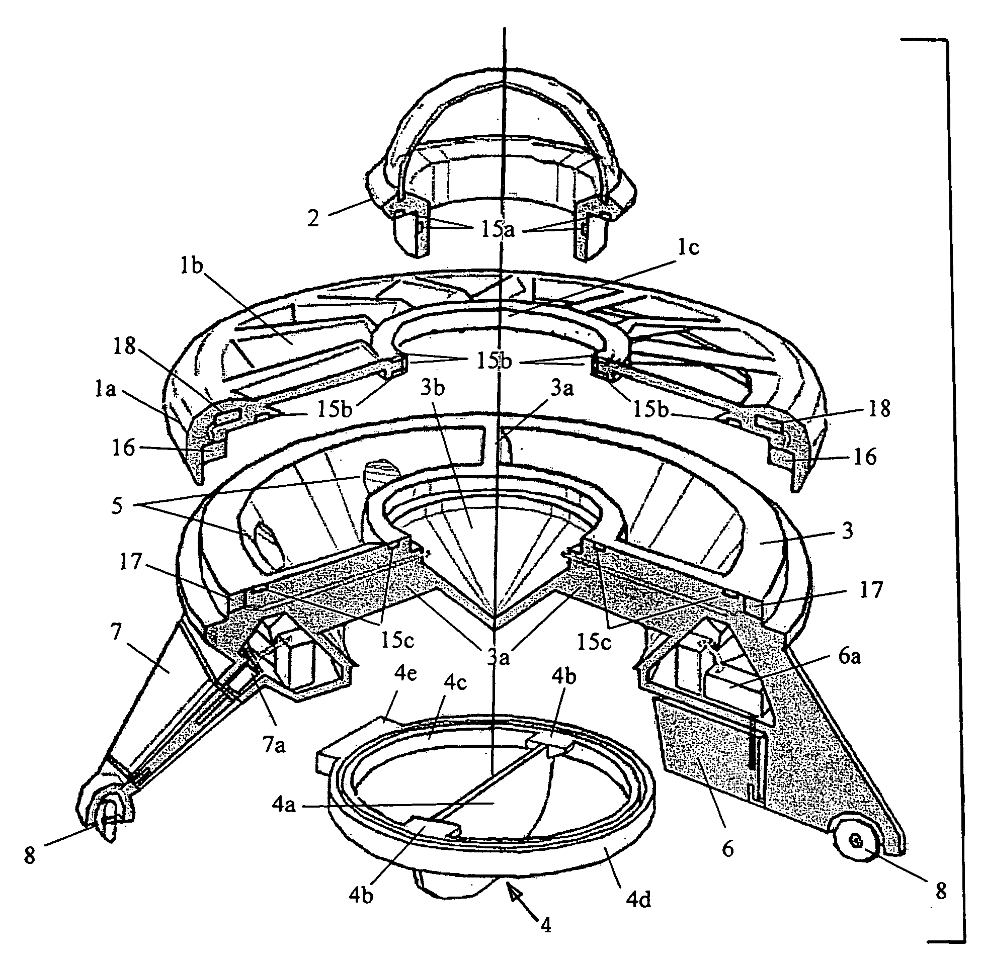
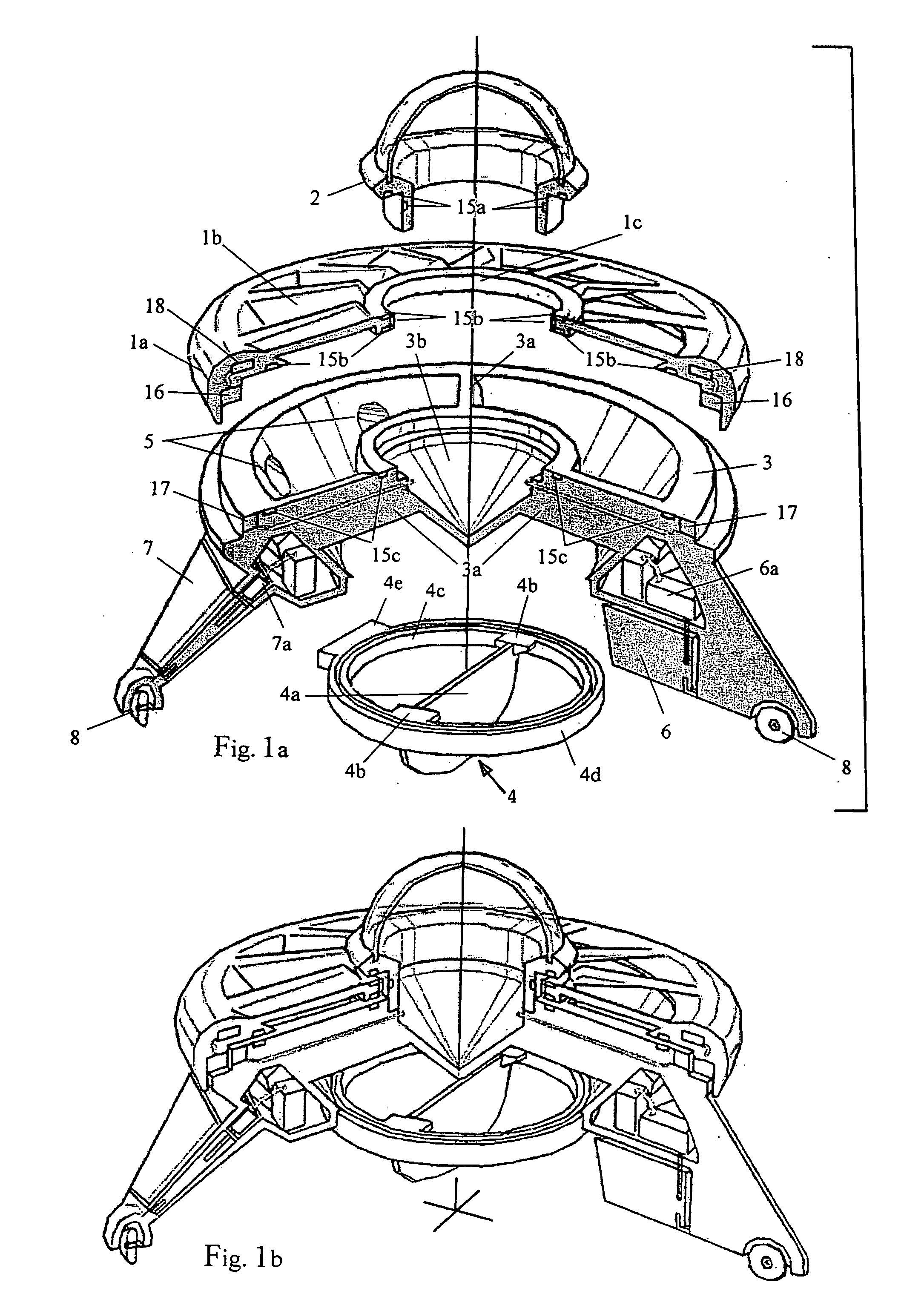
[0041] The present invention is directed to an entirely new class of vertical takeoff and landing vehicles based on a novel engine design using a ducted, magnetic induction air-impeller rotor. The novel engine design provides high gyroscopic stability which allows it to be used in various types of vehicle designs having high maneuverability and ease of flight controls. For simplicity, a basic explanation is given of the magnetic induction air-impeller engine as used in a single-engine design for the VTOL aircraft, followed by description of other variations of the engine design and multi-engine VTOL aircraft designs.

[0042] In FIG. 1a, a single-engine embodiment of an unmanned aerial vehicle in accordance with the present invention has an annular or disk-shaped top cap 1a of a main body or fuselage formed with air intake slots 1b and inner ring support 1c for a transparent dome 2 for housing unmanned surveillance equipment therein. The top cap 1a is nested on the main body or fusela...


PUM


Abstract

A hover aircraft employs an air impeller engine having an air channel duct and a rotor with outer ends of its blades fixed to an annular impeller disk that is driven by magnetic induction elements arrayed in the air channel duct. The air-impeller engine is arranged vertically in the aircraft frame to provide vertical thrust for vertical takeoff and landing. Preferably, the air-impeller engine employs dual, coaxial, contra-rotating rotors for increased thrust and gyroscopic stability. An air vane assembly directs a portion of the air thrust output at a desired angle to provide a horizontal thrust component for flight maneuvering or translation movement. The aircraft can employ a single engine in an annular fuselage, two engines on a longitudinal fuselage chassis, three engines in a triangular arrangement for forward flight stability, or other multiple engine arrangements in a symmetric, balanced configuration. Other flight control mechanisms may be employed, including side winglets, an overhead wing, and/or air rudders or flaps. An integrated flight control system can be used to operate the various flight control mechanisms. Electric power is supplied to the magnetic induction drives by high-capacity lightweight batteries or fuel cells. The hover aircraft is especially well suited for applications requiring VTOL deployment, hover operation for quiet surveillance, maneuvering in close air spaces, and long duration flights for continuous surveillance of ground targets and important facilities requiring constant monitoring.

Description

[0001] This continuation-in-part (CIP) U.S. patent application claims the priority of U.S. Design patent application Ser. No. 29 / 175,100 filed on Jan. 22, 2003, entitled “Quiet Vertical Take Off & Landing (VTOL) Aircraft”, of the same inventors.TECHNICAL FIELD [0002] This present invention relates to manned and unmanned vertical takeoff and landing (VTOL) vehicles, and particularly to a ducted, magnetic induction engine used in such VTOL aircraft for vertical, hover and horizontal flight, and to an air vane assembly, steering assemblies, and other flight contols for maneuvering and controlling translational movement of such VTOL vehicles. BACKGROUND OF INVENTION [0003] There are generally three types of VTOL configurations under current development: wing type configuration having a fuselage with rotatable wings and engines or fixed wings with vectored thrust engines for vertical and horizontal translational flight; helicopter type configuration having a fuselage with a rotor mounted...

Claims


Application Information

Patent Timeline
IPC IPC(8): B64C29/00B64C15/00B64C39/02
CPCB64C27/12B64C27/20B64C39/024B64C2201/127B64C2201/042B64C2201/108B64C2201/027B64U10/13B64U50/19B64U30/20B64U2101/30
Inventor SANDERS, JOHN K. JR.SANDERS, J. KENNETHAVILES, ARTURO JR.AVILES, ARTURO F.
Owner SANDERS JR JOHN K
Why Eureka
Try Eureka