Image display unit and method for driving the same
a display unit and image technology, applied in the direction of cathode-ray tube indicators, static indicating devices, instruments, etc., can solve the problems affecting the display characteristics and abnormal display of high brightness lines in a horizontal direction on the screen, so as to prevent the effect of affecting the selection of the cathode devi
- Summary
- Abstract
- Description
- Claims
- Application Information
AI Technical Summary
Benefits of technology
Problems solved by technology
Method used
Image
Examples
first embodiment
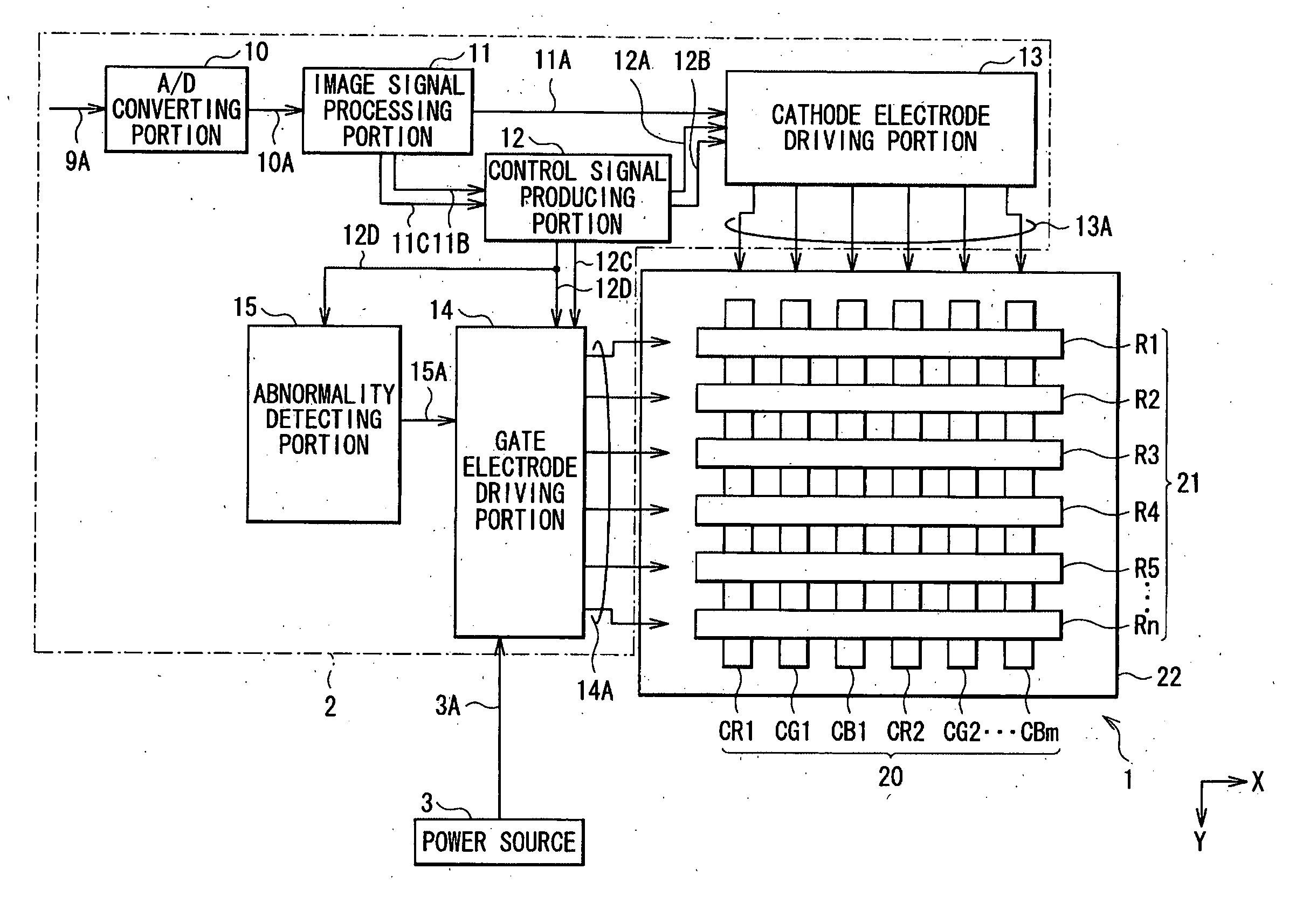
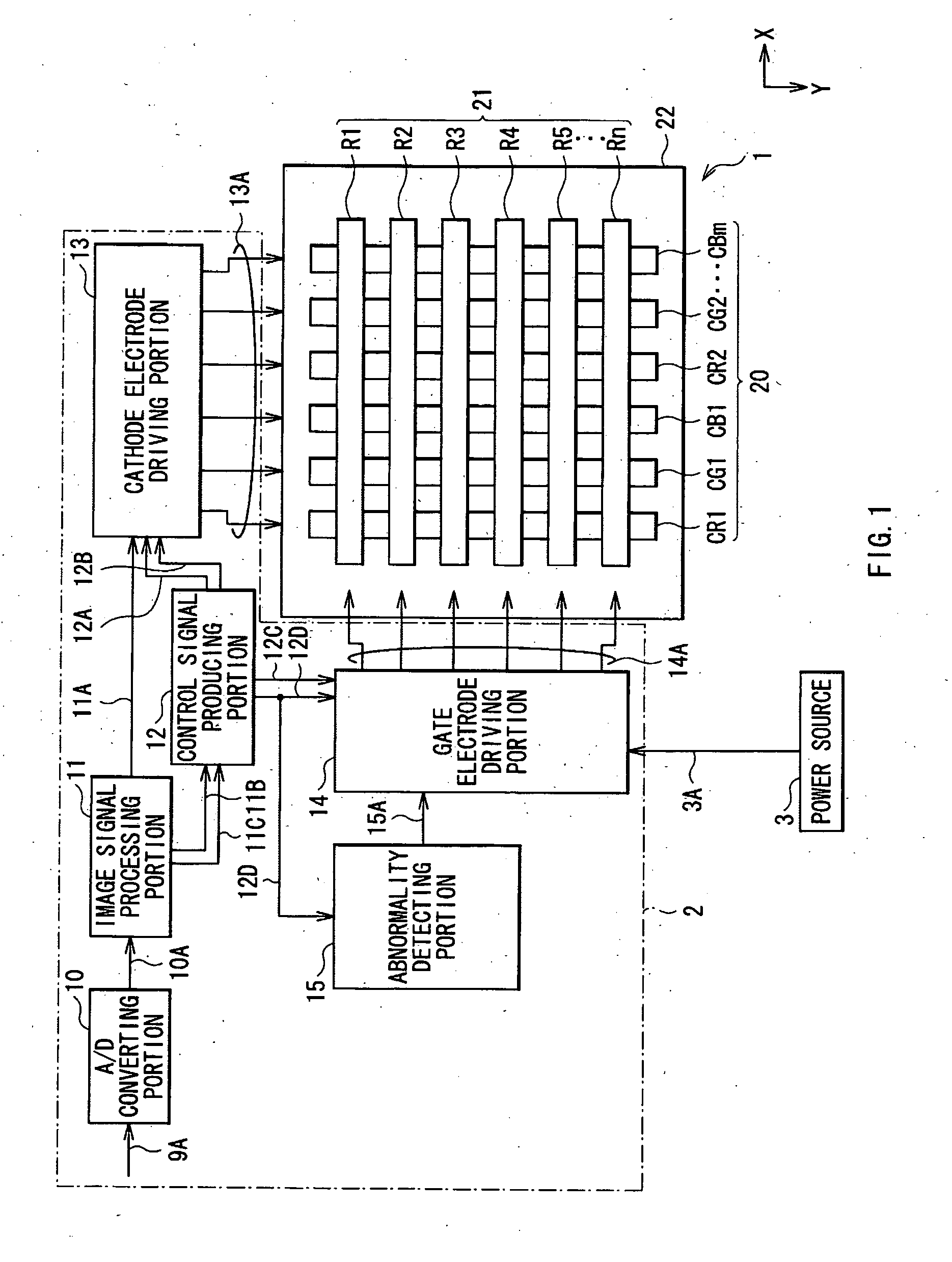
[0060]FIG. 1 shows a schematic block diagram of an image display unit according to a first embodiment of the invention. A method of driving an image display unit according to the embodiment is exemplified by the image display unit according to the embodiment, so the method will be also described below.
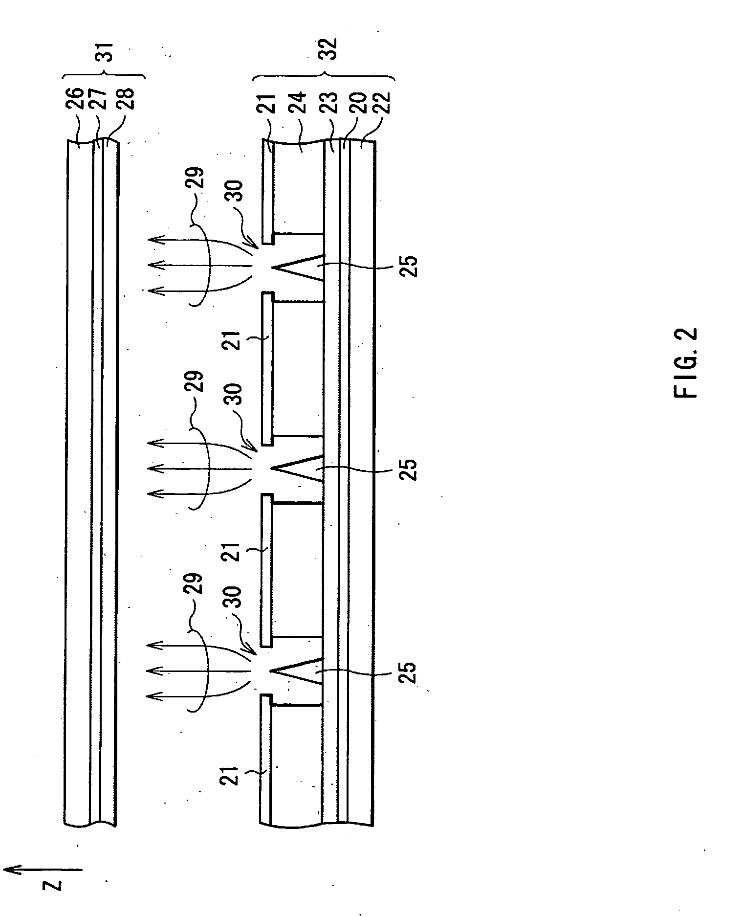
[0061] The image display unit includes an image display device 1 for displaying an image, a device driving portion 2 for driving the image display device 1 and a power source 3 for supplying power to the device driving portion 2. FIG. 2 shows a sectional view of the image display device 1 taken along a plane perpendicular to a row direction (an X axis) and a, column direction (a Y axis). Moreover, FIG. 3 shows a partially enlarged perspective view of the image display device 1. In the embodiment, the case where a passive matrix is used as a driving system will be described as an example. In the following description, “top” indicates a positive direction of a direction (a Z axis) perpe...
second embodiment
[0108] Next, a second embodiment of the invention will be described below.
[0109] In the first embodiment, in the case where an abnormality occurs in the shift clock for gate electrode selection 12D, the output of the gate electrode applied voltage 14A is suspended through suspending the output of the output enable signal 15A which means enabling to output the gate electrode applied voltage 14A. On the other hand, in the embodiment, in the case where the above-described abnormality occurs, the output of a gate electrode applied voltage 44A is suspended through suspending the output of an input enable signal 15C which means enabling to input an input voltage (a gate voltage 3A) from the power source 3.
[0110] In other words, the embodiment differs in including a switch, which can turn on or off the input voltage (the gate voltage 3A) from the power source 3 according to the input enable signal 15C inputted from the abnormality detecting portion 15, between the power source 3 and the ...
third embodiment
[0119] Next, a third embodiment of the invention will be described below.
[0120] The purpose of the first embodiment is to suspend the output from the gate electrode driving portion 14 to the gate electrode 21 in the case where an abnormality occurs in the shift clock for gate electrode selection 12D. On the other hand, the purpose of the embodiment is to suspend the output from the gate electrode driving portion 14 to the gate electrode 21 in the case where an abnormality occurs in the gate electrode driving portion 14.
[0121] The embodiment differs from the first embodiment in including an abnormality detecting portion 45 instead of the abnormality detecting portion 15, and changing a connection relationship between the abnormality detecting portion 45, the control signal producing portion 12 and the gate electrode driving portion 14. The same structures, operations and functions as those in the first embodiment will not be further described, and the above-described differences wi...
PUM
 Abstract
Description
Claims
Application Information
 - R&D
- Intellectual Property
- Life Sciences
- Materials
- Tech Scout
- Unparalleled Data Quality
- Higher Quality Content
- 60% Fewer Hallucinations
Browse by: Latest US Patents, China's latest patents, Technical Efficacy Thesaurus, Application Domain, Technology Topic, Popular Technical Reports.
© 2025 PatSnap. All rights reserved.Legal|Privacy policy|Modern Slavery Act Transparency Statement|Sitemap|About US| Contact US: help@patsnap.com


