Fiber having increased filament separation and method of making same

a technology of fiber and filament, applied in the field of new fiber, can solve the problems of unrealized flock, achieve the effect of increasing the surface area of an amount, increasing the anchoring strength of flock or staple within a part, and increasing the filament separation

Active Publication Date: 2006-03-09
TORAY FLUOROFIBERS AMERICA
View PDF9 Cites 10 Cited by
  • Summary
  • Abstract
  • Description
  • Claims
  • Application Information

AI Technical Summary

Benefits of technology

[0009] A further primary object of the present invention is to provide a fluoropolymer or carbon fiber flock or staple prepared from a yarn, the flock or staple exhibiting improved filament separation.
[0022] When the processed fluoropolymer or carbon fiber of the present invention is mixed with a resin and molded into a part, the properties imparted to the part by including the fiber are enhanced or improved over the properties imparted by the prior art or unprocessed fiber, including for example, when the fiber is a fluoropolymer fiber, increasing the resistance of the part to chemicals, oxidation, moisture, weathering, ozone or ultraviolet radiation and decreasing the amount of energy required to slide the part along an object. Thus, the processed fluoropolymer fiber can be used to impart these improved properties in electrical components, chemical processing equipment and in coatings for cooking utensils, pipes, bearings, bushings, fabrics, filters and gaskets. Specific applications are described, for example, in U.S. Pat. No. 6,695,734 (rubber belts); U.S. Pat. No. 6,506,491 (friction applications such as bearings, bushings and seals); U.S. Pat. No. 6,299,939 (diaphragms for use in an electrolytic cells); U.S. Pat. No. 6,180,574 (self-lubricating bearings and coatings) and U.S. Pat. No. 5,527,569 (filter media for forming filter cloth, filter bags and filter cartridges). With regard to carbon fiber, the processed carbon fiber can be used, for example, to make electrodes for fuel cells and carbon paper and for reinforcing composites.

Problems solved by technology

As a result, when used in different applications, the full benefits of including the flock are not realized, since the flock does not distribute evenly across or through an article and since the multifilament bundles do not present their full potential surface area on or within the article.

Method used


Image

  • Fiber having increased filament separation and method of making same
  • Fiber having increased filament separation and method of making same
  • Fiber having increased filament separation and method of making same

Examples


example 1

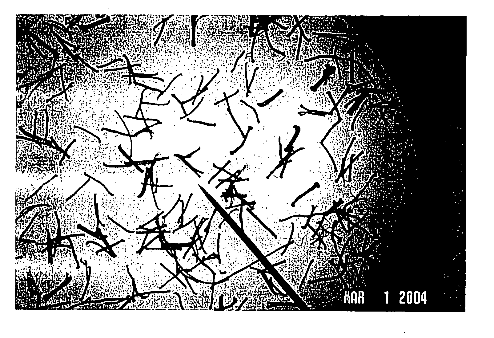
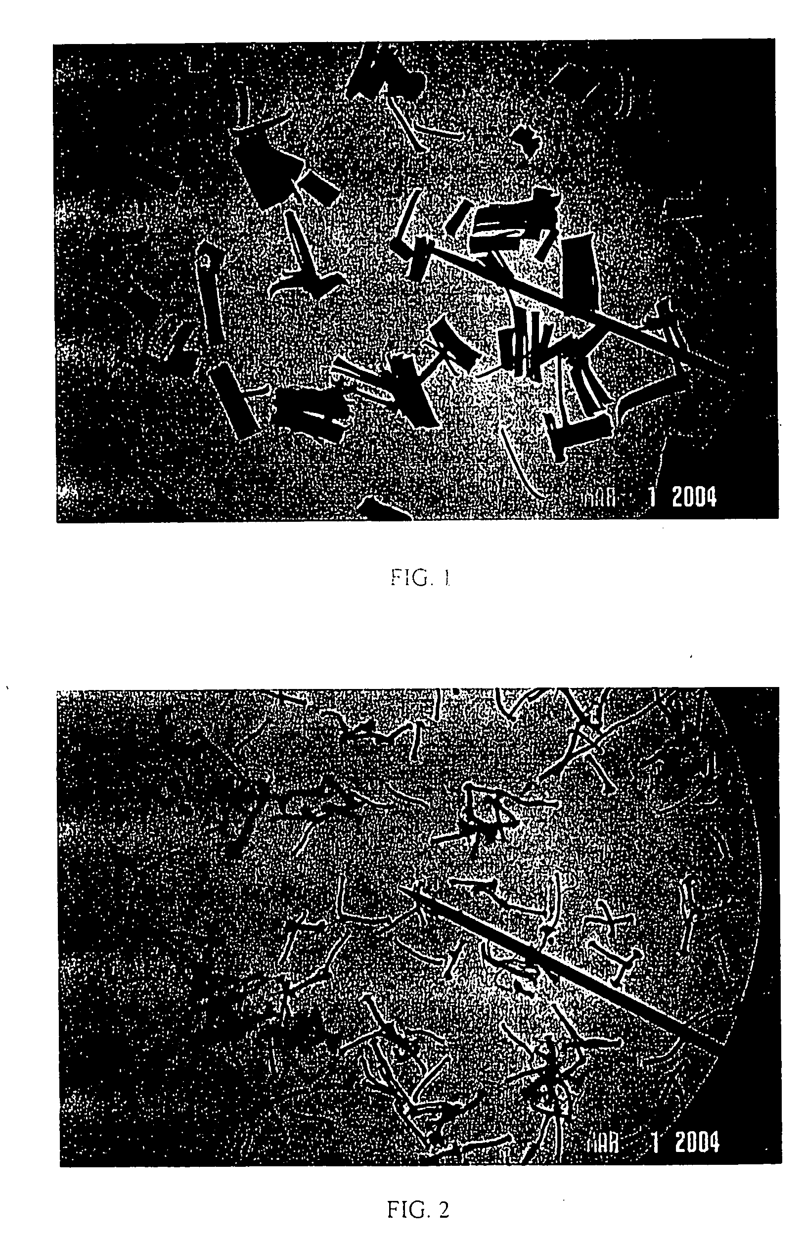
[0049] The dispersion disk and classifier were set to rotate at 6,000 rpm and 2,800 rpm, respectively. The temperature of the room was 60° F. The pressure differential generated by the fan between the fan and the APCM was 15 atm, i.e., −7 atm in the APCM and −22 atm at the fan. As depicted in FIG. 2, the milled flock exhibited an increased degree of filament separation over the un-milled flock depicted in FIG. 1. However, the flock included many fibrils giving the flock fibers a frayed or torn appearance. Additionally, a number of the fibers exhibited frayed ends giving the fibrils a bulbous or pom-pom shaped ends.

example 2

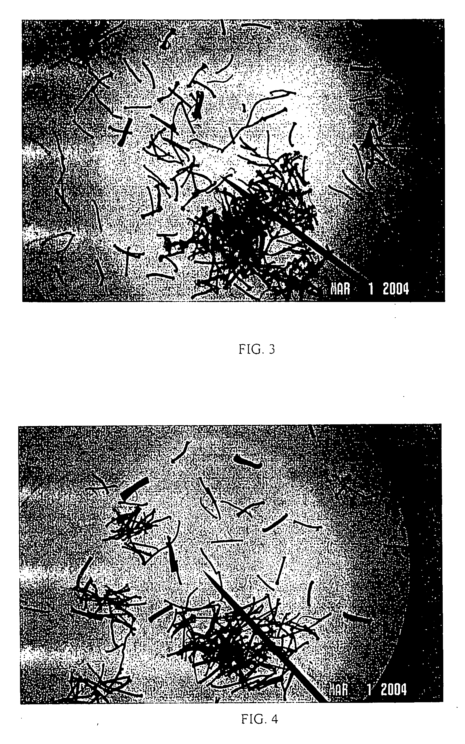
[0050] The dispersion disk and classifier were set to rotate at 6,000 rpm and 2,500 rpm, respectively. The temperature of the room was 60° F. The pressure differential generated by the fan between the fan and the APCM was 15 atm, i.e., −7 atm in the APCM and −22 atm at the fan. As depicted in FIG. 3, the milled flock exhibited an increased degree of filament separation over the un-milled flock depicted in FIG. 1. Like in Example 1, the milled flock included many fibrils, and many of the flock fibers were torn or frayed, giving the fibers a fuzzy appearance and pom-pom shaped ends.

example 3

[0051] The dispersion disk and classifier were set to rotate at 5,000 rpm and 2,000 rpm, respectively. The temperature of the room was 60° F. The pressure differential generated by the fan between the fan and the APCM was 15 atm, i.e., −7 atm in the APCM and −22 atm at the fan. As depicted in FIG. 4, the milled flock exhibited an increased degree of filament separation over the un-milled flock depicted in FIG. 1 but not as much separation as found in Examples 1 and 2. Thus multifilament pieces were seen, primarily double filament pieces. Though some fibrils were apparent, as some of the fibers were torn or frayed, less were torn or frayed than were seen in Examples 1 and 2.


PUM

PropertyMeasurementUnit
diameteraaaaaaaaaa
diameteraaaaaaaaaa
lengthaaaaaaaaaa

Abstract

A flock material exhibiting an increased degree of filament separation prepared by cutting a fluoropolymer or carbon fiber yarn into lengths, introducing mechanical energy into the lengths in order to cause the lengths to separate into single-filaments fibers and removing or classifying at least a portion of the single-filament fibers from the lengths in order to obtain a flock having a particular fraction of single-filament, fluoropolymer or carbon fibers.

Description

FIELD OF INVENTION [0001] The present invention relates to a novel fiber and a method for preparation therefore. More particularly, the present invention relates to a flock or staple prepared from a multifilament fiber, the flock or staple having improved filament separation. BACKGROUND OF INVENTION [0002] Flock is a very short or pulverized fiber that can be used to, among other things, form a velvety pattern on cloth or paper, or a covering on metal or plastic. Flock is made from any number of known fibers including natural fibers, such as cotton and wool, as well as from wet or melt spun fibers, such as fluorocarbon polymer (“fluoropolymer”) fiber and carbon fiber. Fluoropolymer fiber flock is used as a friction modifier in many different end uses including electrical components, chemical processing equipment and in coatings for cooking utensils, bushings, bearings, pipes and gaskets. When used as a friction modifier in industrial applications, such as bearings, fluoropolymer fib...

Claims


Application Information

Patent Timeline
Patent Type & Authority Applications(United States)
IPC IPC(8): D02G3/00
CPCD01G1/04D04H1/42D04H1/70Y10T428/2904D21H13/50D21H15/06Y10T428/29D21H13/04D04H1/4242D04H1/4318Y10T428/23943
Inventor MIWA, KISHIOWINTERS, ERIC WILLIAM
Owner TORAY FLUOROFIBERS AMERICA
Why Eureka
Try Eureka