Efficient ultrasound system for two-dimensional c-scan imaging and related method thereof

Active Publication Date: 2006-03-09
UNIV OF VIRGINIA ALUMNI PATENTS FOUND
View PDF9 Cites 77 Cited by
  • Summary
  • Abstract
  • Description
  • Claims
  • Application Information

AI Technical Summary

Benefits of technology

[0018] In addition, the present invention enables application of various techniques that are known and/or as cited throughout this document. For example, but not limited thereto, spatial and frequency compounding thereby allowing reductions (i.e. allowing improvements) in image speckle with minimal cost in frame rate (i.e., computation) using one technique sometimes known as receive-only compounding. Focus data from different active apertures may be invoked, detected and combined to use the speckle reduced image. Using the present invention this technique can be applied with no cost in image acquisition rate.
[0019] In short, the present invention provides a low cost, efficacious means for producing 2D C-scans and/or collecting 3D image data using 2D arrays. The savings may be realized in the form, but not limited thereto, of any desired combination of lower cost, reduced size, enhanced resolution and improved imaging penetration. Unlike prior art systems and conventional beamforming approaches, the present invention can enable commercially feasible 2D array based C-Scan forming ultrasound imaging systems for non-invasively assisting in routine clinical operations other applications as desired or required.
[0020] In one aspect, the present i

Problems solved by technology

The insertion of needles may also be further complicated in some people whose veins are not readily apparent from the skin's surface, for example, in people with thick layers of fat or infants whose veins are small and difficult to detect.
In other circumstances involving shock, arteries that need to be accessed to sample blood gasses shrink in response and thus become even more difficult to detect.
For some situations, it may be necessary to surgically cut through the body in order to access the desired internal features, a process that is risky and may cause unnecessary delays to treatment.
While the B-scan can be swept through a volume of tissue and the user can, in principle, visualize the three-dimensional (3D) anatomy, such visualization requires significant training and experience.
A beamforming processor becomes much more complex when a 2D sensor array is used.
Not only does the number of time delay operations increase as the square of the size of the array, but also the physical structures required to connect each sensor to its corresponding delay becomes increasingly complex.
The complexity is increased by the need for continuous operation.
Since the speed of so

Method used


Image

  • Efficient ultrasound system for two-dimensional c-scan imaging and related method thereof
  • Efficient ultrasound system for two-dimensional c-scan imaging and related method thereof
  • Efficient ultrasound system for two-dimensional c-scan imaging and related method thereof

Examples


Example

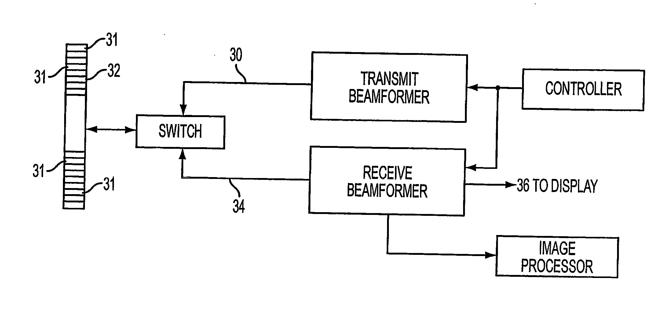
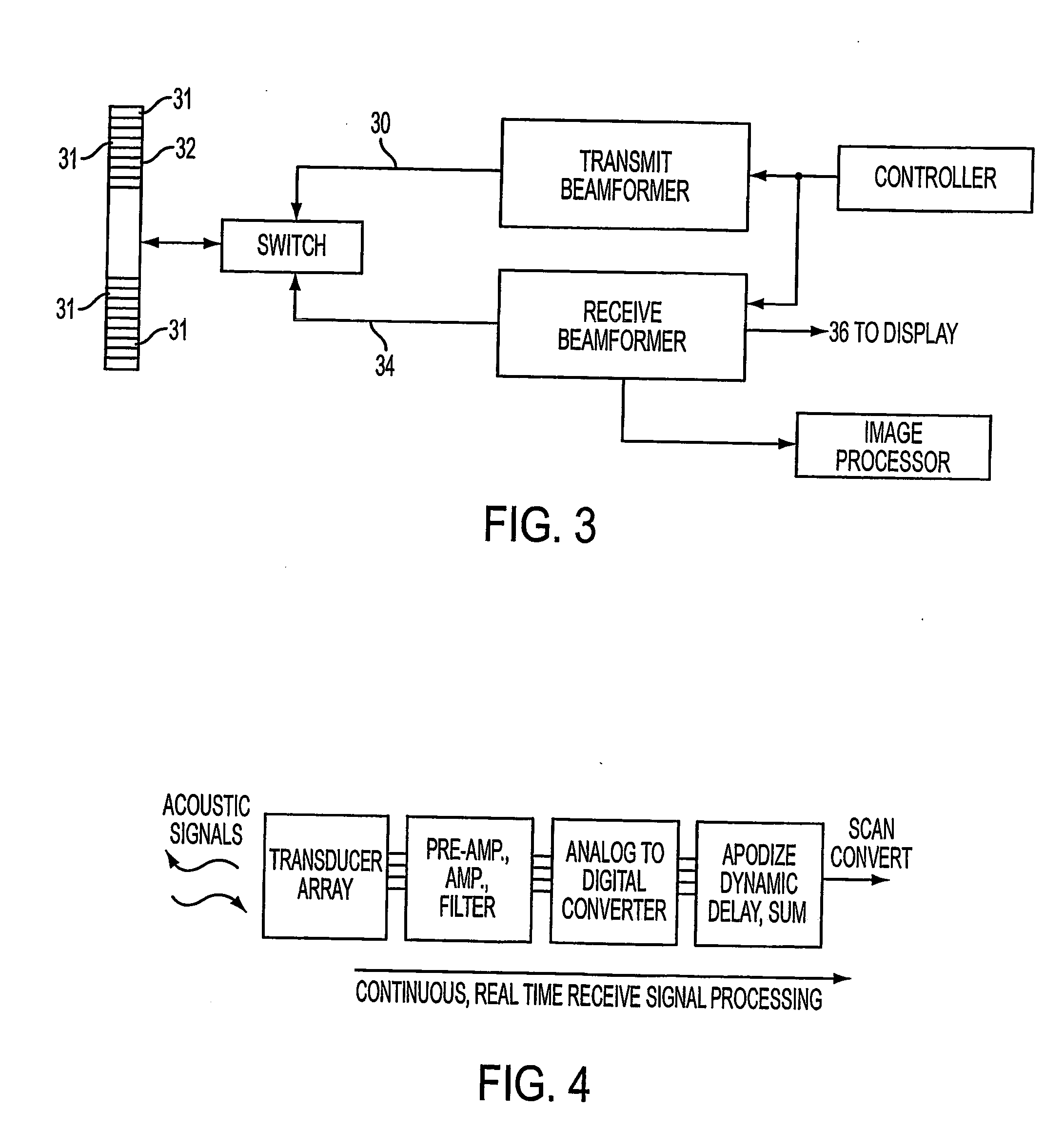
[0031]FIG. 3 illustrates a conventional beamforming system. A transmit generator 30 applies transmit voltage energy signals to an array of transducers 32 having multiple elements 31. The elements 31 of the transducer each receive the transmit electrical signals and generate respective ultrasonic pressure (acoustic) signals. Conventional beamforming operations are applied for each firing of signals. The timing of the firings may be configured to produce one tightly focused beam, multiple transmit beams or may essentially unfocused depending on the beamforming approach being used. For example, a flat, plane wave is used in transmit in the system and method provided in International Application No. PCT / US03 / 06607, filed Mar. 6, 2003, entitled “An Intuitive Ultrasonic Imaging System and Related Method Thereof,” of which is assigned to the present assignee and is hereby incorporated by reference herein in its entirety. Conventional beamforming also involves the procedure of apodization f...


PUM


Abstract

An ultrasound system and related method for forming 2D C-scan images and/or collecting 3D image data from 2D transducer arrays. The system including in part a 2D transducer array of elements, transmit voltage generation means for each element, a memory buffer with or part of channels for each element, and a receive beamformer. On a time serial or sequential basis, several times for each line of firing, the contents of the per element memory buffer are read into the beamformer with different focusing values for each buffer reading cycle. In this way, the beamformer can calculate beamformed image values for multiple points per line firing cycle—or per each line of signals between the transducer array and receive beamformer.

Description

CROSS-REFERENCES TO RELATED APPLICATIONS [0001] The present invention claims priority from U.S. Provisional Application Ser. No. 60 / 440,262 filed Jan. 15, 2003, entitled Efficient Electronic Hardware for C-scan Planes with 2D Arrays in Diagnostic Ultrasound and Related Method Thereof,” the entire disclosure of which is hereby incorporated by reference herein in its entirety. [0002] The present application is also related to International Application No. PCT / US03 / 06607, filed Mar. 6, 2003, entitled “An Intuitive Ultrasonic Imaging System and Related Method Thereof,” of which is assigned to the present assignee and is hereby incorporated by reference herein in its entirety. The present invention may be implemented with the technology discussed throughout aforementioned International Application No. PCT / US03 / 06607. [0003] The present application is also related to PCT International Application No. PCT / US04 / ______, filed Jan. 14, 2004 (attorney docket no. 3053-118, which claimed priorit...

Claims


Application Information

Patent Timeline
IPC IPC(8): A61B8/00A61B8/02G01SG01S15/89
CPCA61B8/13A61B8/483G01S15/8993G01S7/52095G01S15/8925G01S7/52085
Inventor HOSSACK, JOHN A.WALKER, WILLIAM F.BLALOCK, TRAVIS N.
Owner UNIV OF VIRGINIA ALUMNI PATENTS FOUND
Why Eureka
Try Eureka