

Sliding door insert for portable pet portal
a door insert and portable technology, applied in the field of sliding door inserts for portable pet portals, can solve the problems of poor insulation quality, too large for young pets, too small for pets, etc., and achieve the effect of convenient location, effective weather sealing, and effective weather sealing
- Summary
- Abstract
- Description
- Claims
- Application Information
AI Technical Summary
Benefits of technology
Problems solved by technology
Method used
Image

Examples
Embodiment Construction
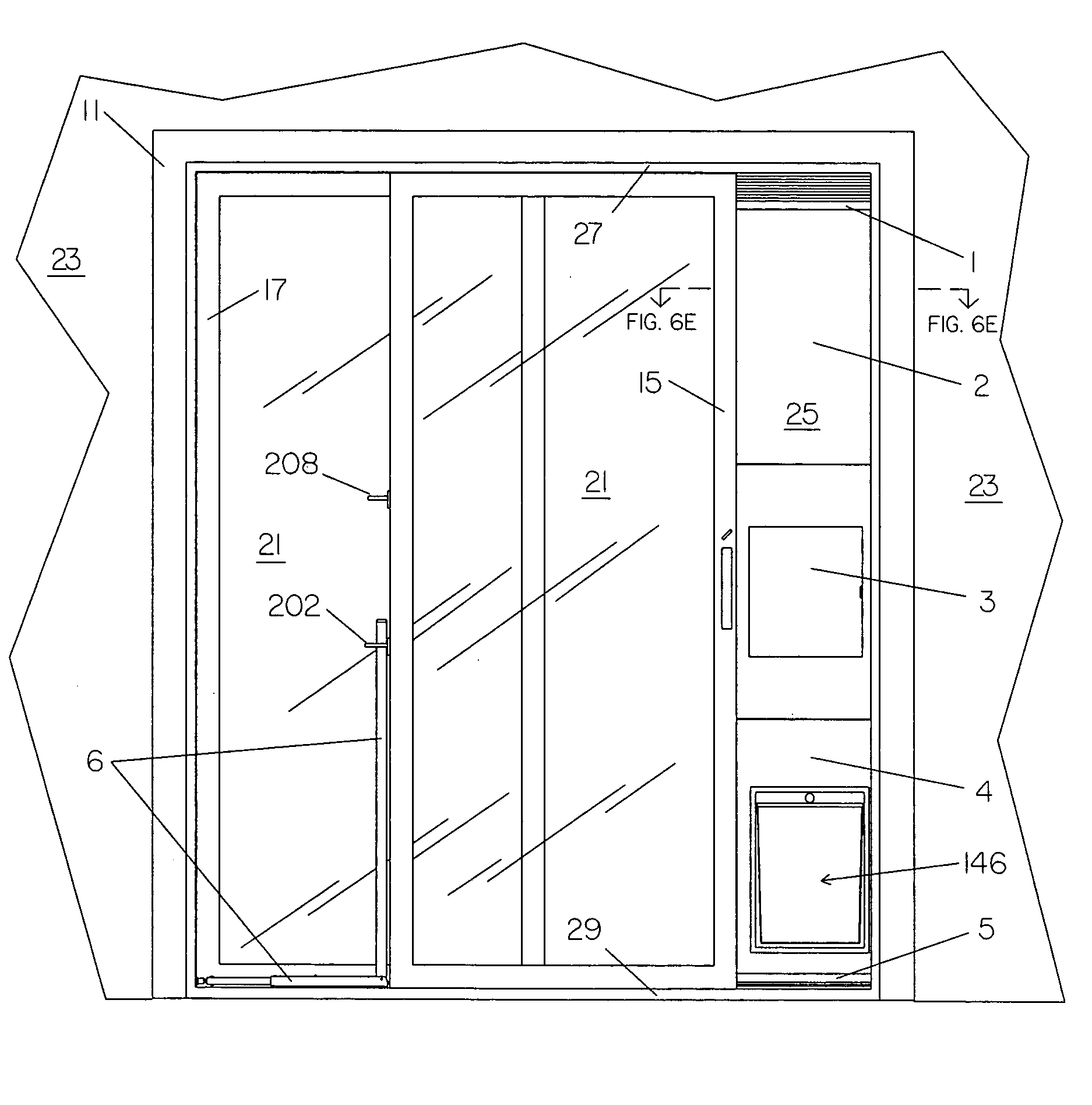
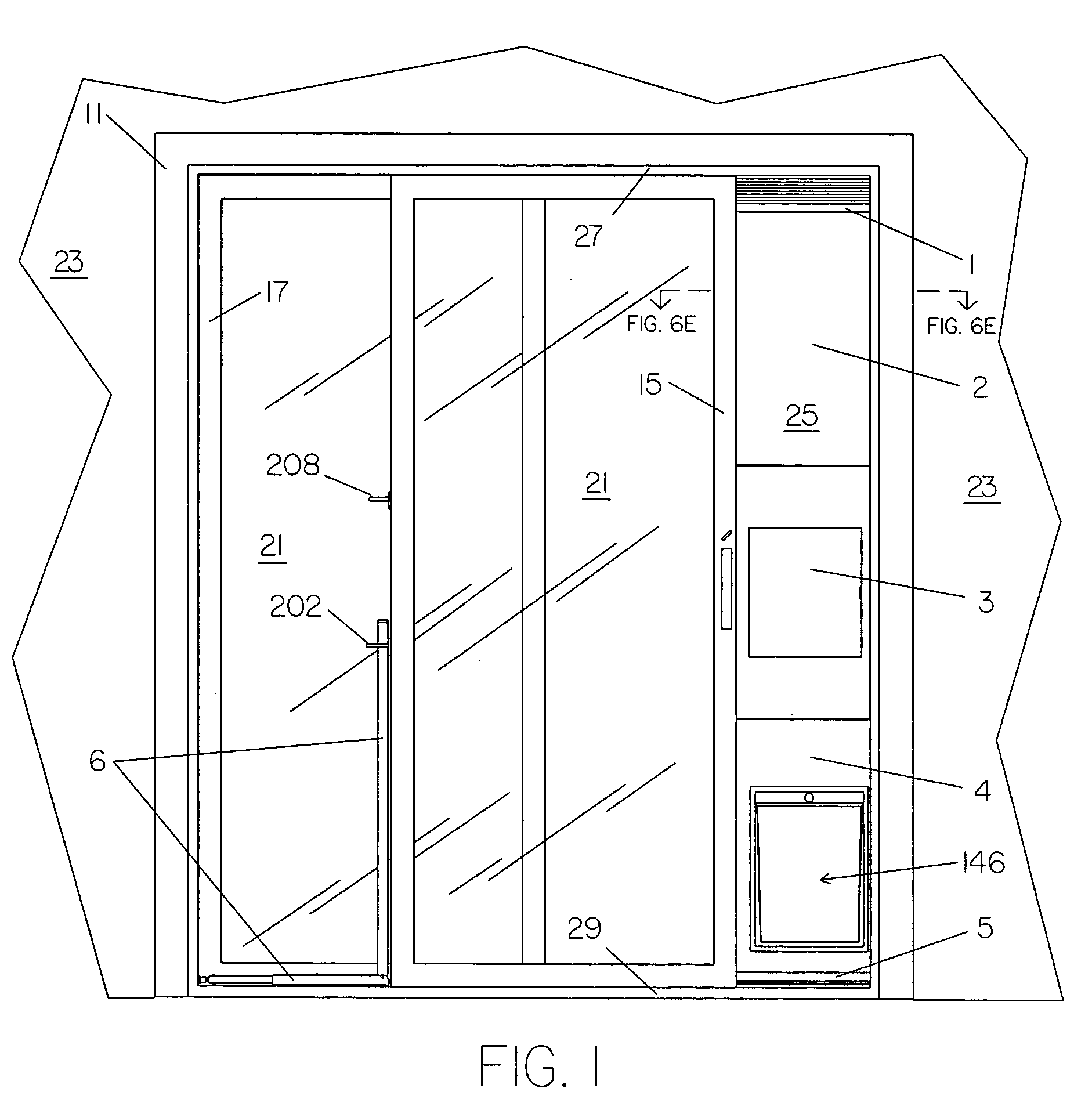
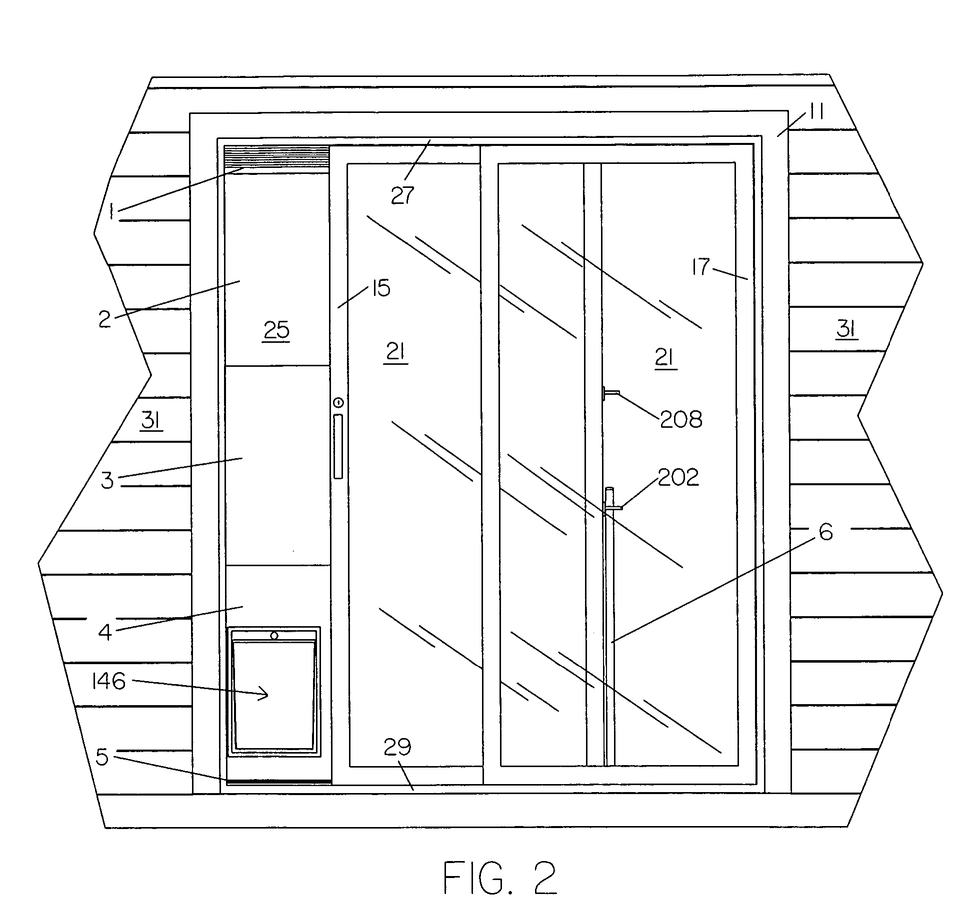
[0142] As shown in FIGS. 1-3, the preferred embodiment of the invention, pet door panel 25, is installed between the sliding door frame 11, and the leading side of frame 15 on movable sliding door 21, to provide a means of ingress and egress for a pet. Drop lock security lock 6 is installed on the interior side of stationary sliding door 21, between sliding door frame 11, and the trailing side of frame 15 on movable sliding door 21, to secure pet door panel 25 between sliding door frame 11 and the leading side of frame 15 on movable siding door 21, to prevent movable sliding door 21 from being opened with pet door panel 25 installed. Sliding door frame 11 is typically secured to a building structure 23, such as a home or office. For illustrative purposes all elevational views, except as noted, depict the sliding glass patio door in a right opening configuration. Therefore, when describing various elements of the invention reference made to right and left side views pertains to insta...
PUM
 Abstract
Description
Claims
Application Information