Liquefied gas-delivering device for diesel engine

a technology of liquefied gas and diesel engines, which is applied in the direction of liquid fuel feeders, machines/engines, electric control, etc., can solve the problems of large vibration and noise, diesel engines cannot be normally started, and the combustion is abnormal, so as to reduce the time taken

Inactive Publication Date: 2006-03-16
BOSCH AUTOMOTIVE SYST CORP
View PDF8 Cites 17 Cited by
  • Summary
  • Abstract
  • Description
  • Claims
  • Application Information

AI Technical Summary

Benefits of technology

[0061] After the stop of the diesel engine, the feed pipe opening/closing means is controlled to be closed and cut off the supply of the liquefied gas fuel to the fuel gallery, and when the feed pump is stopped with the suction port opening/closing means closed, the fuel gallery and the overflow fuel pipe are separated from the feed pipe and the aspirator. Then, the above-mentioned purge pipe opening/closing means is opened to cause the low-pressure tank and the overflow fuel pipe to communicate

Problems solved by technology

As a result, vaporized DME fuel is charged in the cylinder, and when the diesel engine is to be started at the next time, there is a risk that abnormal combustion such as knocking occurs and the diesel engine cannot be normally started and large vibrations and noise occur.
Accordingly, in a fuel supply system for a diesel engine, there is a risk that means for retrieving remaining fuel after the stop of the fuel supply device becomes expensive and the main cause of increasing the cost of the fuel supply system.
However, the present inventor has promoted further intensive research and discovered that if the liquefied gas fuel remaining in the injection system of the liquefied gas fuel supply device after the stop of the diesel engine is to be sucked into the fuel tank by the suction means using the aspirator, a comparatively long time is required to suck all the liquefied gas fuel remaining in the injection system.
This is because the suction force by the aspirator having no driving source is wea

Method used


Image

  • Liquefied gas-delivering device for diesel engine
  • Liquefied gas-delivering device for diesel engine
  • Liquefied gas-delivering device for diesel engine

Examples


first embodiment

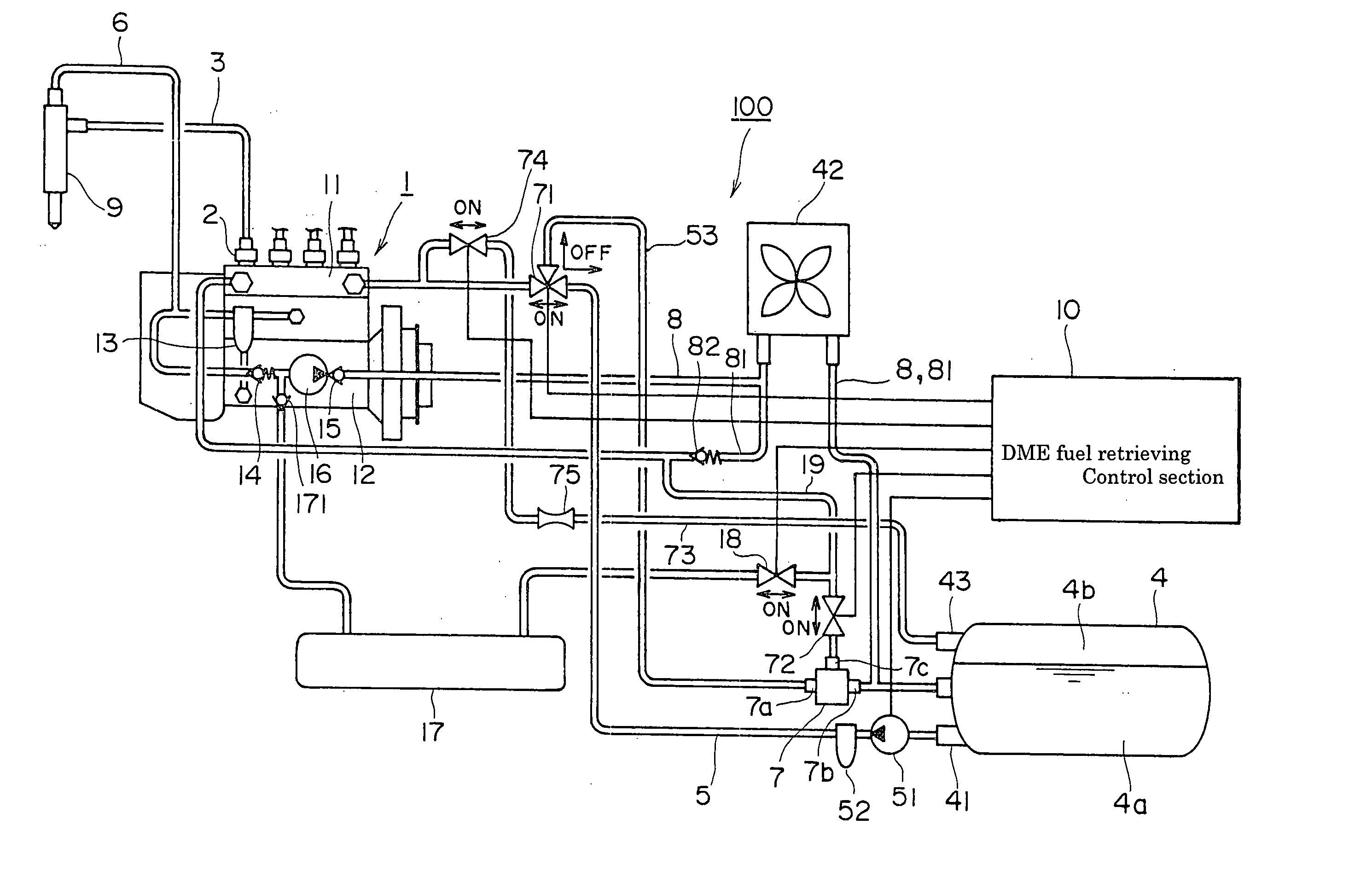
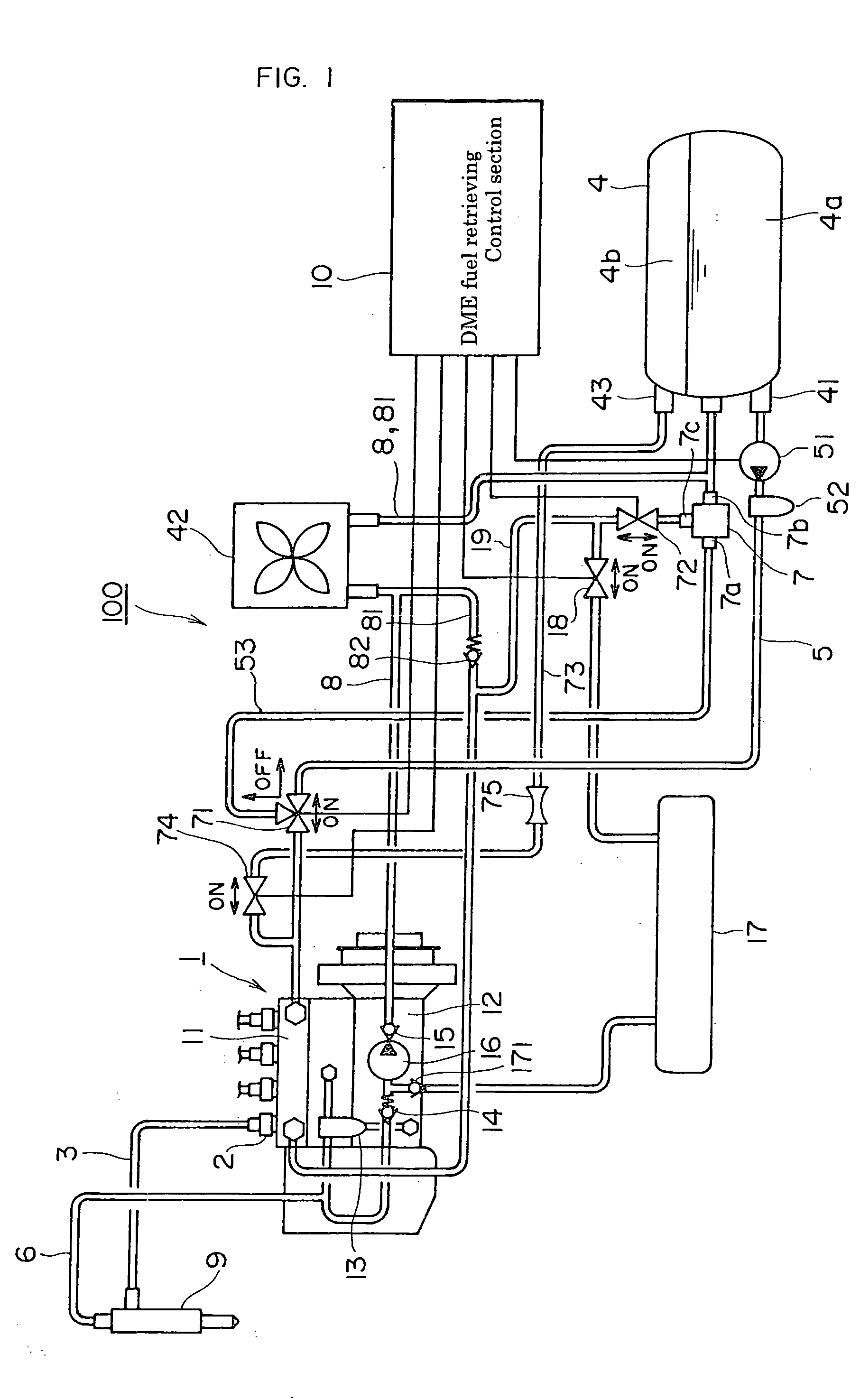
[0078] First, a schematic structure of a liquefied gas fuel supply device for a diesel engine will be described. FIG. 1 is a schematic diagram showing a liquefied gas fuel supply device for a diesel engine according to the invention of the present application.

[0079] A liquefied gas fuel supply device 100 which supplies liquefied gas fuel to a diesel engine has an injection pump 1. Representative examples of liquefied gas fuel are DME and high cetane number LP gas (LP gas to which a cetane number improver is added) having a cetane number of approximately 40-55, desirably, 50 or higher. In embodiments which will be described later, reference will be made to examples in which DME is used as liquefied gas fuel. Incidentally, when high cetane number LP gas is used, a known material such as a nitric ester, a nitrite and an organic peroxide are used as a cetane number improver. A specific cetane number improver is DTBP (Di-tertiary butyl peroxide) or 2HEN (2-Ethylhexylnitrate). In addition...

embodiment 3

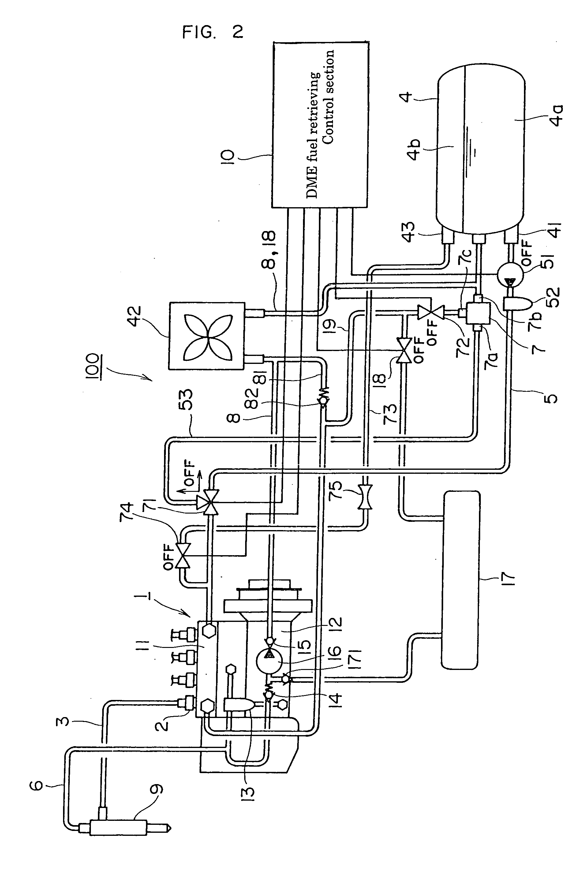
[0107] Furthermore, in the DME fuel supply device 100 for a common rail diesel engine, as shown in FIG. 7, the vapor-phase pressure delivery pipe 73 may also be connected to the vicinity of the injection nozzle 9 of the injection pipe 3 (the inlet side of the injection nozzle 9) (embodiment 3). If the vapor-phase pressure delivery pipe 73 is connected in this manner to the vicinity of the injection nozzle 9 of the injection pipe 3 disposed at a position far higher than the common rail 91, not only the DME fuel remaining in the common rail 91 but also the DME fuel remaining in the injection pipe 3 can be delivered under pressure directly to the aspirator 7 by vapor phase pressure. Accordingly, it is possible to further reduce time taken to retrieve the DME fuel remaining in the common rail 91 and the injection pipe 3 to the fuel tank 4 by means of the aspirator 7. In addition, since the vapor-phase pressure delivery pipe opening / closing solenoid valve 74 which opens and closes the va...

fifth embodiment

[0109]FIG. 9 is a schematic diagram showing the DME fuel supply device according to the invention.

[0110] The DME fuel supply device 100 for supplying DME fuel to a diesel engine includes an injection pump 1. The injection pump 1 has the same number of injection pump elements 2 as the number of cylinders which the diesel engine has. The feed pump 51 pressurizes DME fuel reserved in the fuel tank 4 to a predetermined pressure and delivers the DME fuel into the feed pipe 5. The DME fuel delivery port 41 of the fuel tank 4 is provided below the level of the liquid phase 4a in the fuel tank 4, and the feed pump 51 is disposed in the vicinity of the DME fuel delivery port 41 of the fuel tank 4. The DME fuel delivered into the feed pipe 5 is filtered by the filter 52, and is delivered to the injection pump 1 via the check valve 713 and the feed pipe opening / closing solenoid valve 711. During an injection state (during the operation of the diesel engine), the feed pipe opening / closing solen...


PUM


Abstract

Since an aspirator 7 is disposed at a position lower than a fuel gallery 11 and an overflow fuel pipe 81, DME fuel remaining in the fuel gallery 11 and the overflow fuel pipe 81 can be more efficiently retrieved to a fuel tank 4 by a combined force of gravity and suction force produced in a suction port 7c of the aspirator 7. Since the vapor-phase pressure delivery pipe opening/closing solenoid valve 74 is disposed at a position higher than the fuel gallery 11, DME fuel in a liquid state remaining in the fuel gallery 11 and the overflow fuel pipe 81 is forcedly delivered under pressure to the suction port 7c of the aspirator 7 by a combined force of gravity and the pressure of a vapor phase 4b in the fuel tank 4. Accordingly, time taken to retrieve the DME fuel in an injection system to the fuel tank after the stop of a diesel engine.

Description

TECHNICAL FIELD [0001] The present invention relates to a liquefied gas fuel supply device for a diesel engine which uses, as fuel, liquefied gas such as DME (dimethyl ether) or LP gas to which a cetane number improver is added (hereinafter referred to as “high cetane number LP gas”). BACKGROUND ART [0002] A diesel engine which uses clean-burning fuels such as DME (dimethyl ether) and high cetane number LP gas instead of light oil is now attracting attention as air pollution abatement measures for diesel engines. These fuels are liquefied gas fuels unlike light oil which is a conventional fuel. Namely, liquefied gas fuels have boiling points lower than that of light oil, and have the nature of vaporizing at room temperature, whereas light oil exists as a liquid under atmospheric pressure at room temperature. For this reason, in the case of a diesel engine using liquefied gas fuel, after the stop of the diesel engine, liquefied gas fuel remaining in an injection system which is a fue...

Claims


Application Information

Patent Timeline
IPC IPC(8): F02M21/02F02B3/06F02D19/08F02M21/06F02M21/08F02M53/00F02M55/00F02M63/00
CPCF02B3/06Y02T10/36F02D41/042F02D41/3863F02D2250/02F02M21/0212F02M21/06F02M37/025F02M53/00F02M55/00F02M2200/40Y02T10/32F02D19/0621F02M21/0224F02M21/0236F02M21/0245F02D41/0027Y02T10/30F02M37/00F02M21/08F02M47/02
Inventor NOZAKI, SHINYANODA, TOSHIFUMIUSHIYAMA, DAIJIISHIKAWA, TERUAKIHAYASAKA, YUKIHIRO
Owner BOSCH AUTOMOTIVE SYST CORP
Why Eureka
Try Eureka