Exhaust heat recovery muffler

a technology of exhaust heat recovery and mufflers, which is applied in the direction of functional valve types, machines/engines, light and heating apparatus, etc., can solve the problems of limited space for disposing devices under the floor of automobiles, difficult to provide sufficient space, and device size, and achieve the effect of simple and compact structure, simple and compact structure of exhaust heat recovery mufflers, and simple and compact structur

Inactive Publication Date: 2006-03-16
FUTABA IND CO LTD
View PDF6 Cites 80 Cited by
  • Summary
  • Abstract
  • Description
  • Claims
  • Application Information

AI Technical Summary

Benefits of technology

[0013] The exhaust heat recovery muffler of the present invention comprises a muffler unit, having the outer surface thereof covered, and an exhaust heat recovery unit disposed integrally with the muffler unit. The exhaust heat recovery muffler furthermore comprises a switching valve that switches the flow of exhaust gas into the muffler unit and into the exhaust heat recovery unit. Hence, according to the present invention, the structure of the exhaust heat recovery muffler can be simple and compact. The exhaust heat recovery muffler of one aspect of the present invention is provided with a heat exchange chamber, which is formed by partitions and s

Problems solved by technology

Therefore, the space to dispose devices under the floor of an automobile is limited.
It is difficult to provide sufficient space for the conventional exhaust gas heat recovering device disclosed in JP 2000-204941, because the structure thereof is complicated and the size of the device is large, due to the heat

Method used


Image

  • Exhaust heat recovery muffler
  • Exhaust heat recovery muffler
  • Exhaust heat recovery muffler

Examples


second embodiment

[0035] Referring now to FIGS. 3 and 4, the following describes a second embodiment of the present invention.

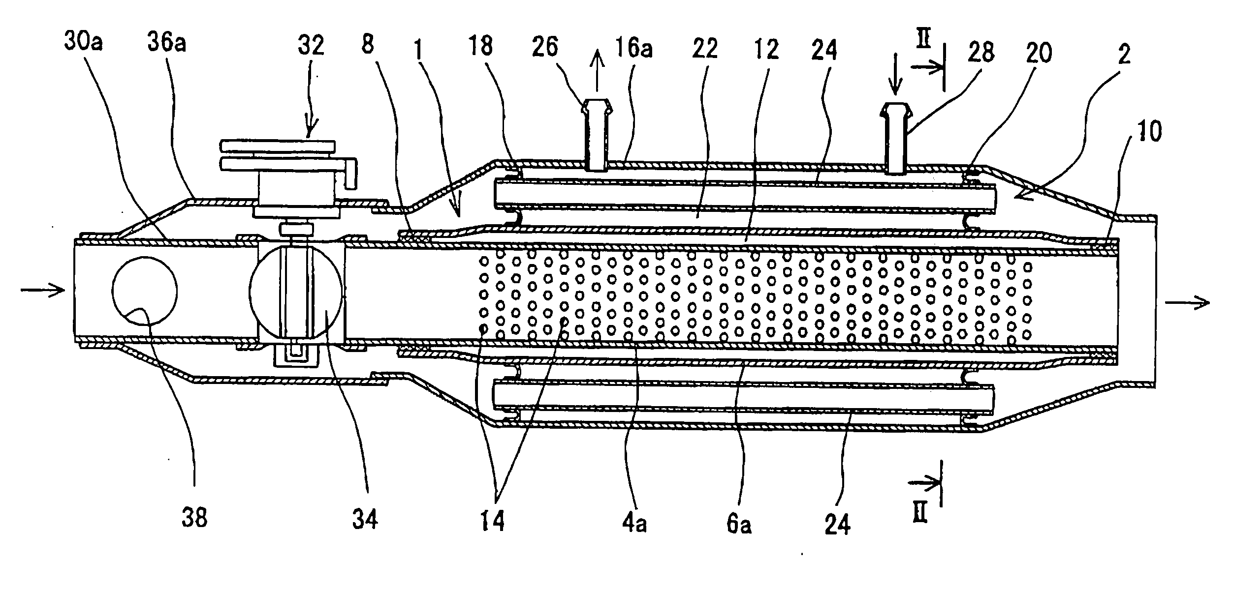
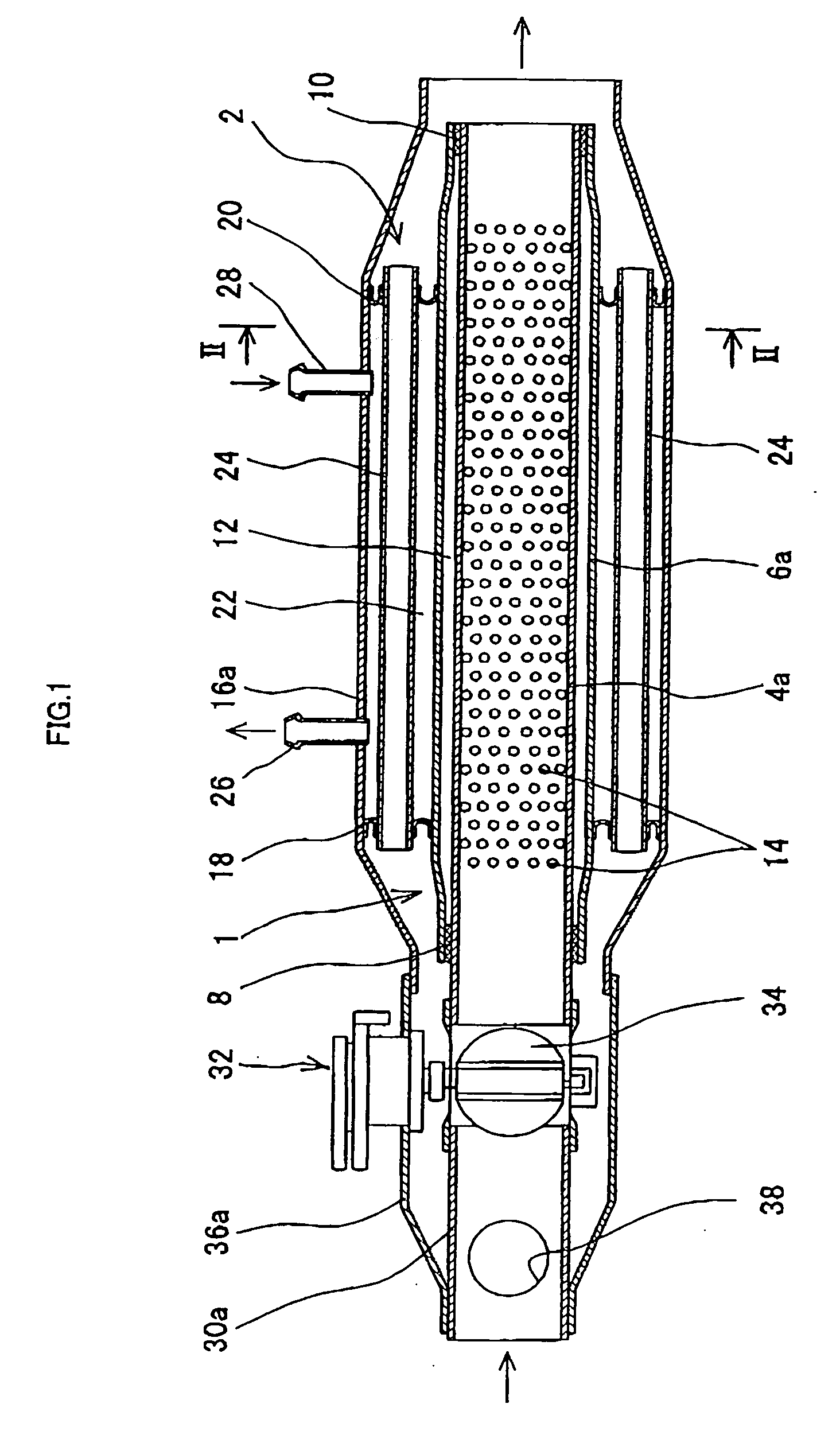
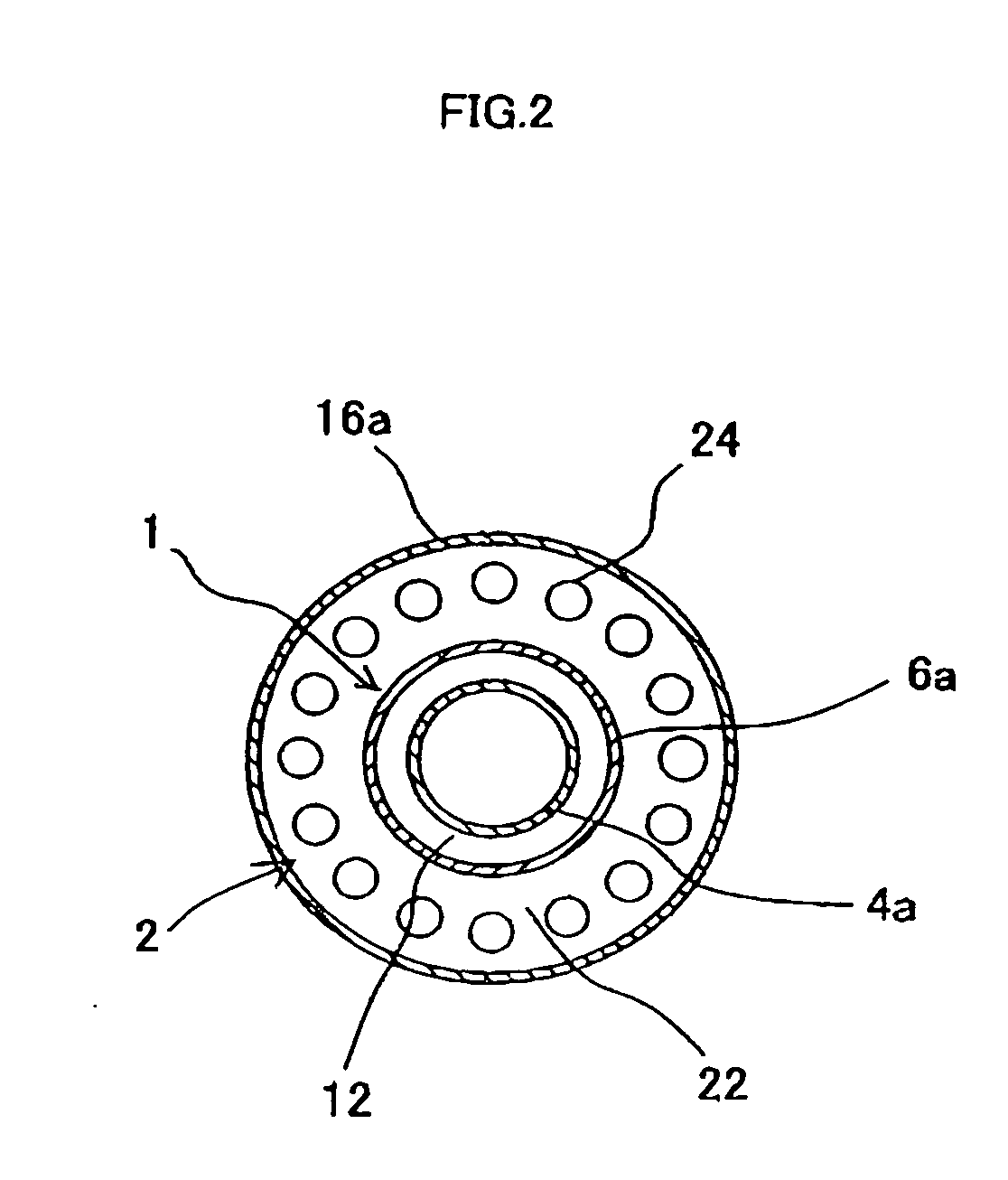
[0036] As shown in FIG. 3, reference numeral 1 indicates a muffler unit. Reference numeral 2 indicates an exhaust heat recovery unit. The muffler unit 1 comprises an inner pipe 4b and an outer pipe 6b. The inner pipe 4b is inserted into the outer pipe 6b so as to be disposed coaxially with the outer pipe 6b. Wire meshes 8 and 10 are provided on both ends of the outer pipe 6b between the inner circumference of the outer pipe 1b and the outer circumference of the inner pipe 4b. A silencing chamber 12 is formed between the inner circumference of the outer pipe 6b and the outer circumference of the inner pipe 4b. Multiple small openings 14 are provided on the inner pipe 4b so as to be communicated with the silencing chambers 12.

[0037] The exhaust heat recovery unit 2 comprises a shell 16b that covers the outer circumference of the outer pipe 6b of the muffler unit 1. The shell 1...

third embodiment

[0053] Referring now to FIGS. 5 and 6, the following describes a third embodiment of the present invention. The basic structure of the exhaust heat recovery muffler according to the present embodiment is the same as the structure of the exhaust heat recovery muffler according to the second embodiment. The same reference numerals are given to the same constituents as in the above-described second embodiment. Detailed description of these constituents is not repeated herein. The same applies to the following embodiment.

[0054] As shown in FIG. 5, both ends of an outer pipe 6c are tapered. Wire meshes 8 and 10 are provided between the inner circumference of the outer pipe 6c and the outer circumference of an inner pipe 4c. A silencing chamber 12 is formed between the inner circumference of the outer pipe 6c and the outer circumference of the inner pipe 4c.

[0055] In an exhaust heat recovery unit 2, a cylindrical outer jacket 17b and a cylindrical inner jacket 19b are provided between t...

fourth embodiment

[0063] Referring now to FIGS. 7 and 8, the following describes a fourth embodiment of the present invention.

[0064] As shown in FIG. 7, the upstream side of an outer pipe 6d is tapered, and the inner circumference thereof is sealed onto the outer circumference of the inner pipe 4c. The downstream side of the outer pipe 6d is also tapered. However, a wire mesh 10 is provided between the inner circumference of the outer pipe 6d on the downstream side and the outer circumference of the inner pipe 4c. A silencing chamber 12 is formed between the inner circumference of the outer pipe 6d and the outer circumference of the inner pipe 4c.

[0065] In an exhaust heat recovery unit 2, a cylindrical outer jacket 17c and a cylindrical inner jacket 19c are provided between the outer circumference of the outer pipe 6d and the inner circumference of the shell 16b so as to be respectively coaxial with the shell 16b.

[0066] As shown in FIG. 8, the cross-sectional surface of the outer and the inner jac...


PUM


Abstract

The exhaust heat recovery muffler includes a muffler unit having the outer surface thereof covered, an exhaust heat recovery unit disposed integrally with the muffler unit, and a switching valve that switches the flow of exhaust gas into the muffler unit and into the exhaust heat recovery unit. An outer pipe of the muffler unit and a cylindrical shell of the exhaust heat recovery unit, covering the outer circumference of the outer pipe, are coaxially disposed. The exhaust heat recovery unit includes a heat exchange chamber, formed by a pair of partitions provided between the inner circumference of the shell and the outer circumference of the outer pipe, and small-diameter pipes penetrating through the pair of partitions and extending through the heat exchange chamber. A heat exchange medium flows inside of the heat exchange chamber.

Description

BACKGROUND OF THE INVENTION [0001] (1) Field of the Invention [0002] The present invention relates to an exhaust heat recovery muffler that conducts a heat exchange between exhaust gas and a heat exchange medium, a recovery of exhaust heat, as well as a noise reduction. [0003] (2) Background Art [0004] A conventional exhaust heat recovering device is disposed in an exhaust path, and provided with a muffler, having an inner pipe with several small openings and an outer pipe covering the inner pipe, and a heat exchanger disposed inside of the inner pipe to recover heat from the exhaust gas (cf. Unexamined Japanese Patent Publication No. 2000-204941). The heat exchanger is constituted with a pair of plates, which form a path for coolant water, and an inner fin, alternately layered. This conventional device reduces exhaust noise with the muffler and recovers exhaust heat with the heat exchanger. [0005] Another conventional exhaust beat recovery device has an exhaust heat recovery unit t...

Claims


Application Information

Patent Timeline
IPC IPC(8): F16K17/00F01N1/00F01N7/00F01N1/08F01N5/02F01N13/08
CPCF01N1/003F01N1/006F01N1/166F01N5/02F28F2265/28F28D7/103F28D7/1669F28D21/0003Y02T10/16F01N2240/02Y02T10/12
Inventor TAKEMOTO, NAOHIROSUZUKI, YOSHIHIKO
Owner FUTABA IND CO LTD
Why Eureka
Try Eureka