Printed circuit board motor

a printed circuit board and motor technology, applied in the field of electric motors, can solve the problems of limited life of batteries and significant part of the cost of such motors, and achieve the effects of accurate control of rotation rate, torque and average current consumption

Inactive Publication Date: 2006-03-16
TRIMBLE NAVIGATION LTD
View PDF25 Cites 69 Cited by
  • Summary
  • Abstract
  • Description
  • Claims
  • Application Information

AI Technical Summary

Benefits of technology

[0005] In accordance with one embodiment of the present invention, a printed circuit board motor is disclosed. The motor comprises a rotor that comprises a generally circular plate embedded with magnets that extend to the outer edge of the front surface of the rotor plate; an axle coupled to the back surface of the rotor plate; and a stator imprinted with a printed circuit board on its front surface that positioned adjacent and parallel to the front surface of the rotor plate. The printed circuit board comprises two conductors printed on the same surface or on opposite surfaces of the printed circuit board. The conductors are oriented 90° out of phase with each other. The two conductors produce alternating “square wave” patterns. The printed circuit board circuitry causes the direction of the current flow to reverse at prescribed intervals. The magnets embedded in the rotor plate provide a magnetic field that passes through the printed circuit board. The magnets around the edge of the rotor plate alternate north and south poles. The rotor rotates in response to the current flow in the stator. This rotation rate can be accurately controlled. The torque and average current consumption can be controlled by “chopping” the input current with relatively high frequency modulation whose duty cycle is proportional to the torque and average current consumption.
[0006] Accordingly, it is an object of the present invention to provide an inexpensive rotating electric motor that provides accurate control of rotation rate and allows for variable torque and motor current so that during speed changes extra torque and current can be applied, but during steady rotation, current consumption can be reduced, thereby, prolonging battery life.
[0007] It is also an object to increase battery life by reducing motor current to the amount needed to maintain the desired rotation rate, prolonging the battery life of the motor.

Problems solved by technology

Permanent magnet motors typically use batteries which have a limited life to produce the electric current needed to power the conductors.
A significant part of the cost of such motors reside in their wire coils.

Method used


Image

  • Printed circuit board motor
  • Printed circuit board motor
  • Printed circuit board motor

Examples


Embodiment Construction

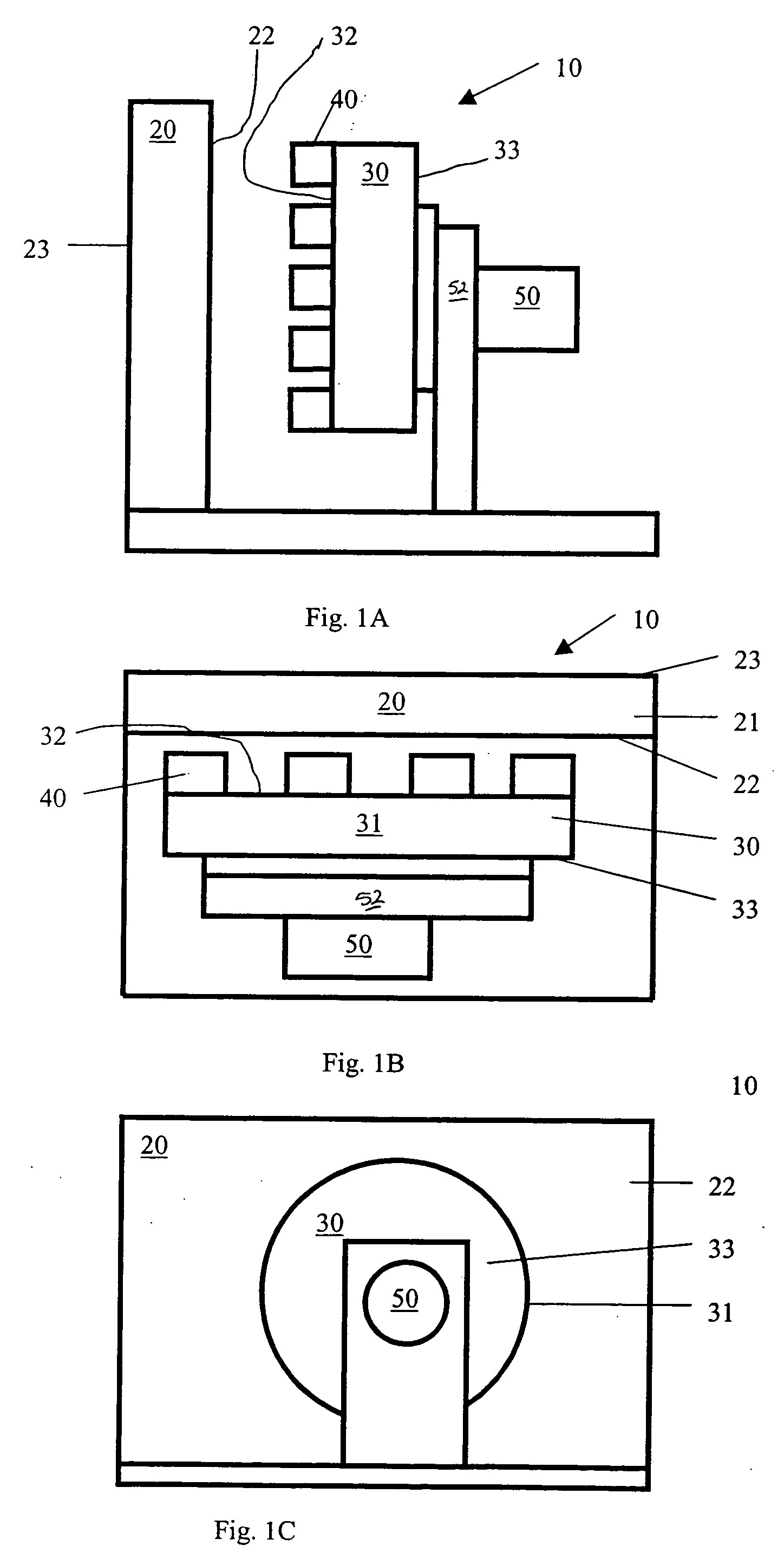
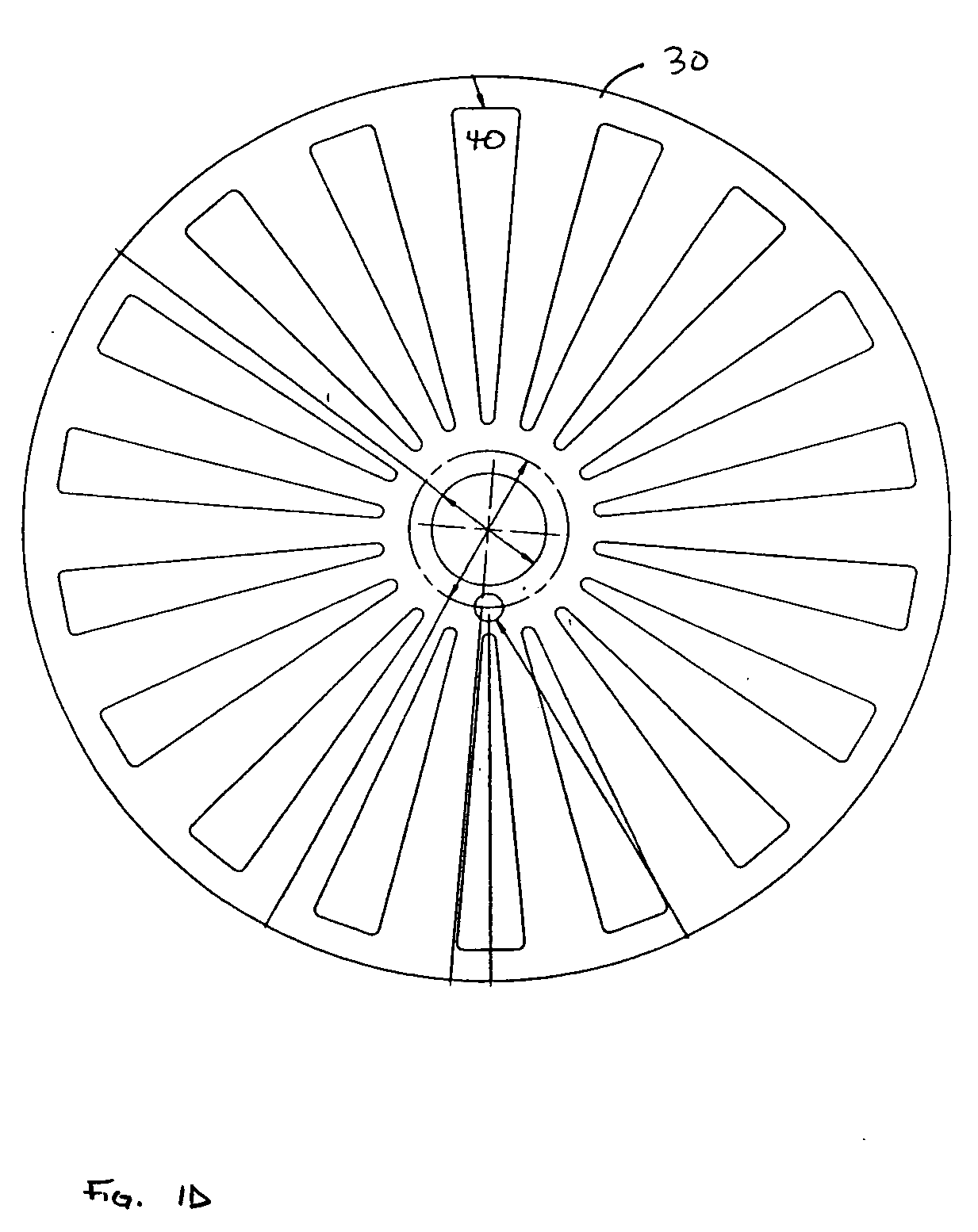
[0021] FIGS. 1A-D diagrammatically illustrate a printed circuit board motor 10 from several different viewpoints. A rotor 30 of the printed circuit board motor 10 comprises a plate 31 having a front surface 32 and a back surface 33. The rotor 30 has a plurality of magnets 40 mounted on and extended to the outer edge of the front surface 32 of the rotor plate 31 as seen in FIG. 1D. The magnets 40 may also be embedded into the front surface 32 of the rotor plate 31. The plurality of magnets 40 on the rotor 30 alternate their north and south poles. That is, proceeding around the periphery of the rotor 30, one encounters magnets with their north poles facing away from the rotor 30 interleaved with magnets with their south poles facing away from the rotor 30. The rotor plate 31 may be configured as a circular disc but other geometric shapes are possible. The rotor 30 is attached to an axle 50. The axle 50 rotates with the rotor 30, and may be attached to whatever apparatus is to be drive...


PUM


Abstract

A printed circuit board motor is disclosed. The motor comprises a rotor plate embedded with magnets, an axle, and a printed circuit board stator. The printed circuit board comprises two conductors printed on the same surface or on opposite surfaces of the printed circuit board The two conductors produce alternating “square wave” patterns. The printed circuit board circuitry causes the direction of the current flow to reverse at intervals. The rotor rotates in response to the current flow in the stator. The rotation rate can be accurately controlled. The torque and average current consumption can be controlled by “chopping” the current with high frequency modulation whose duty cycle is proportional to the torque and average current consumption which will prolong the battery life of the motor.

Description

BACKGROUND OF THE INVENTION [0001] The present invention generally relates to an electric motor incorporating permanent magnets and, in particular, to a motor having a rotor with a series of permanent magnets and a stator configured as a printed circuit board. [0002] Electric motors of the type that include permanent magnets have become ubiquitous and part of everyday life. Such motors have many uses, including rotating small or light-weight parts of equipment in a precisely controlled manner. The basic electric design of this type of motor has not changed significantly over the years. Characteristically, current is switched to a series of conductor coils to produce a rotating field. The magnets in the motor are then acted upon by the rotating field, producing rotation of the rotor. Permanent magnet motors typically use batteries which have a limited life to produce the electric current needed to power the conductors. [0003] It is desirable to incorporate an inexpensive electromagne...

Claims


Application Information

Patent Timeline
Patent Type & Authority Applications(United States)
IPC IPC(8): H02K5/00H02K21/12
CPCH02K3/26H02K11/0073H02P6/002H02K2211/03H02K21/24H02K11/33H02P6/28
Inventor ZALUSKY, JAMES THOMAS
Owner TRIMBLE NAVIGATION LTD
Why Eureka
Try Eureka