
Information processing apparatus and a method of controlling the same

a technology of information processing apparatus and control method, which is applied in the direction of electric digital data processing, instruments, computing, etc., can solve the problems of radiation noise generation, incorrect detection of position coordinates, etc., and achieve the effect of preventing the influence of nois

Inactive Publication Date: 2006-03-16
LAPIS SEMICON CO LTD
View PDF2 Cites 17 Cited by
  • Summary
  • Abstract
  • Description
  • Claims
  • Application Information

AI Technical Summary

Benefits of technology

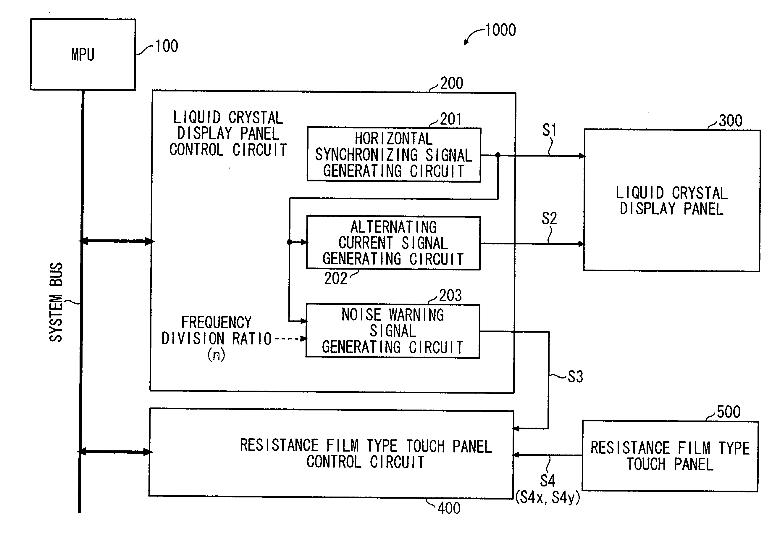
The present invention aims to provide an improved information processing apparatus that prevents the effects of noises that may occur at certain cycles, such as the radiation noise that occurs by the reversal of polarity of the liquid crystal drive voltage of the liquid crystal display panel. The invention includes a resistance film type touch panel, a liquid crystal panel, and first and second control circuits. The first control circuit generates a horizontal synchronizing signal, and the second generating circuit generates an alternating current signal to reverse the polarity of the liquid crystal drive voltage based on the horizontal synchronizing signal. The third generating circuit generates a noise warning signal based on the horizontal synchronizing signal, indicating the interval or timing when the polarity of the liquid crystal drive voltage reverses. The second control circuit changes the predetermined sampling interval or timing based on the noise warning signal, and detects a position coordinate inputted from the resistance film type touch panel at the changed predetermined sampling interval or timing. The technical effect of the invention is to prevent the influence of noises that may occur at certain cycles, such as the radiation noise that occurs by the reversal of polarity of the liquid crystal drive voltage of the liquid crystal display panel.

Problems solved by technology

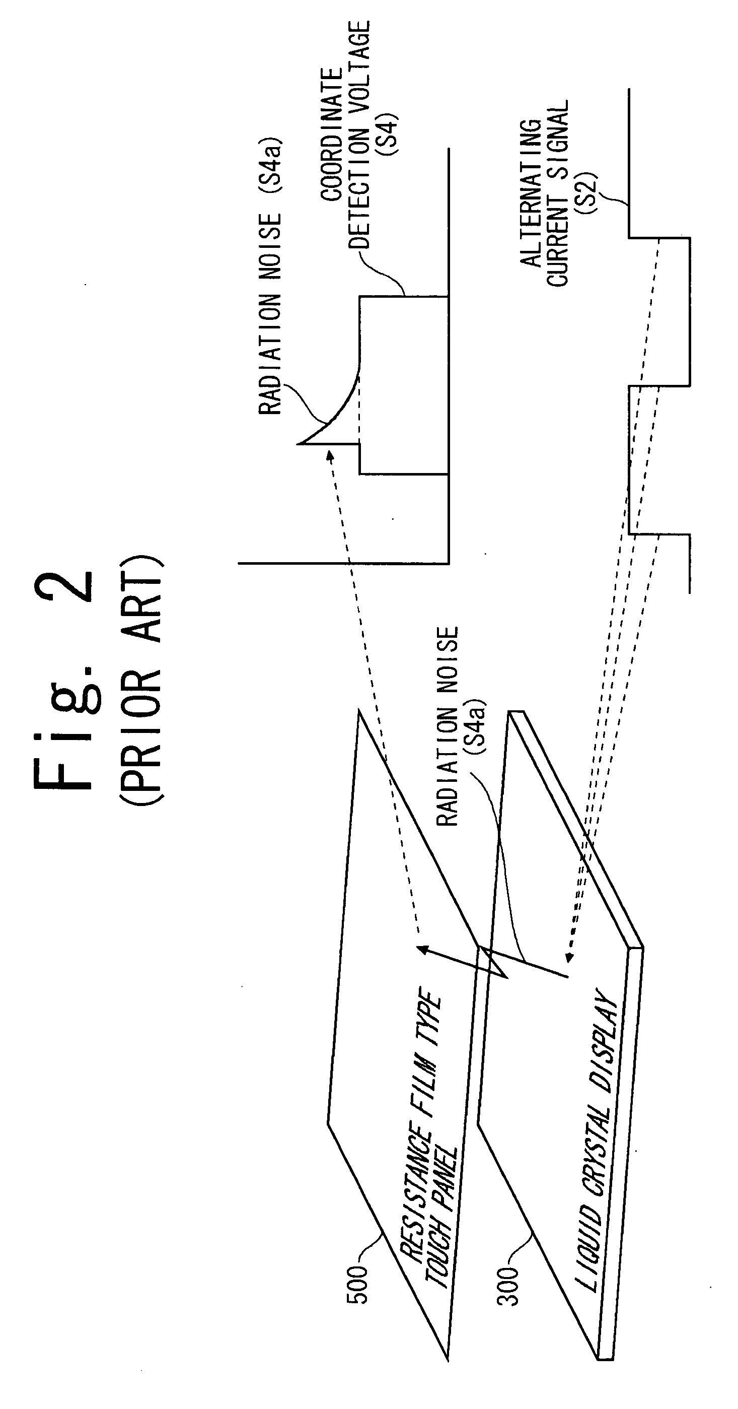
However, when the liquid crystal drive voltage is reversed, radiation noise is generated from the liquid crystal display panel and superimposed on a coordinate detection voltage of the adjacent touch panel.
This causes an incorrect detection of position coordinates.
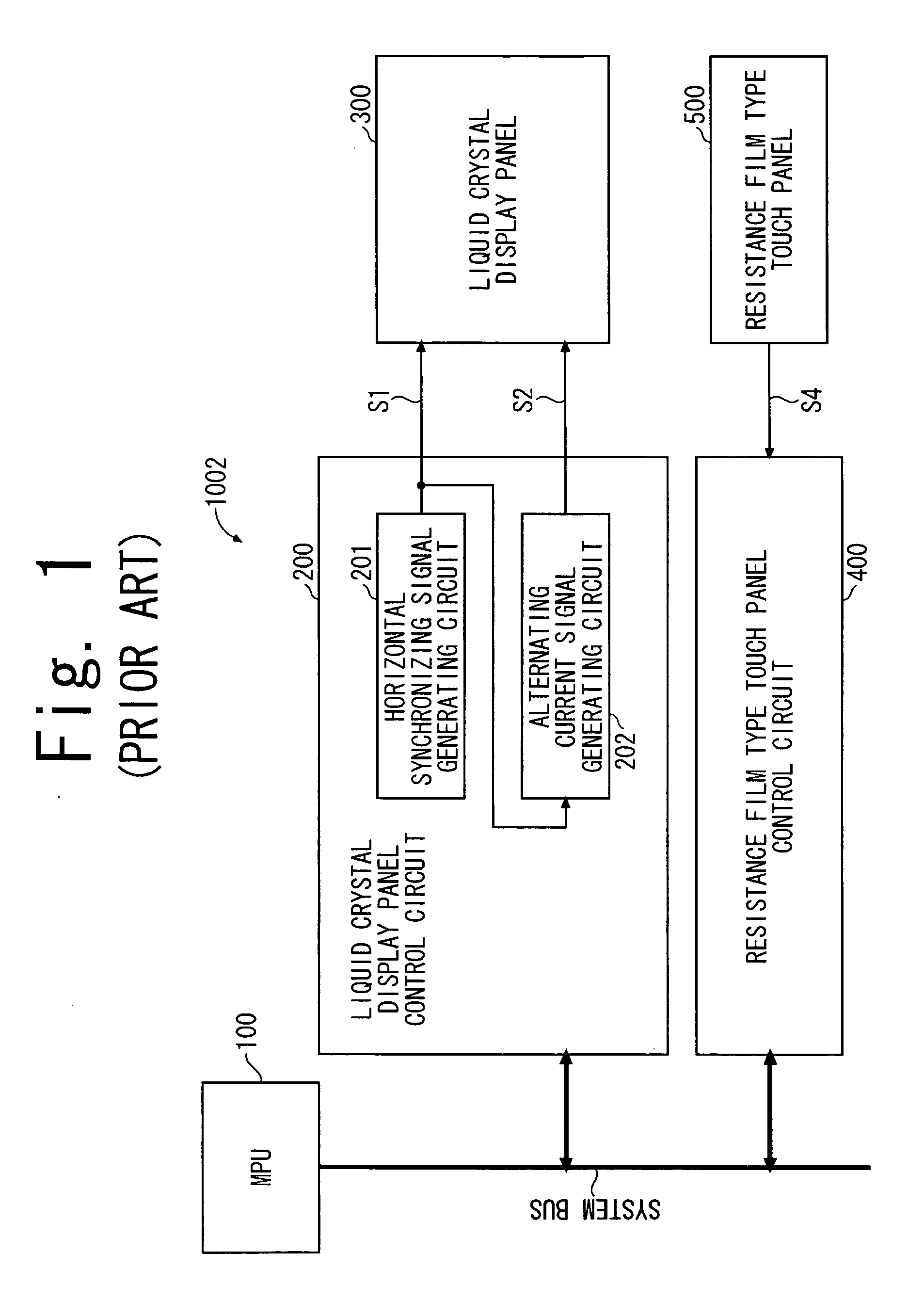
With respect to the structure of the information processing apparatus 1002 shown in FIG. 1, there is a problem, as just mentioned, that the position coordinates in the resistance film type touch panel 500 is detected incorrectly due to the radiation noise generated at the time the polarity of the liquid crystal drive voltage is reversed.
However, this method is not effective in removing noises that are generated at a certain fixed cycle, as the radiation noise accompanied by the reversal of the liquid crystal drive voltage.
In other words, this method is not effective in removing noises whose occurrence can be predicted in advance, because the processing time becomes redundant.

Method used


Image

  • Information processing apparatus and a method of controlling the same
  • Information processing apparatus and a method of controlling the same
  • Information processing apparatus and a method of controlling the same

Examples


first embodiment

(1) First Embodiment

Structure

[0042]FIG. 4 is a view of a schematic block diagram illustrating a system configuration of an information processing apparatus 1000 according to a first preferred embodiment of the present invention. As with the information processing apparatus 1002 shown in FIG. 1, the information processing apparatus 1000 is provided with an MPU 100, a liquid crystal display panel control circuit (first control circuit) 200, a liquid crystal display panel 300, a resistance film type touch panel control circuit (second control circuit) 400, and a resistance film type touch panel 500. In FIG. 4, with regards to identically or similarly structured elements as those of the conventional information processing apparatus 1002 shown in FIG. 1, the same reference numbers as used in FIG. 1 will be used, and redundant explanations of those structure elements will be omitted.

[0043] In the present embodiment, in addition to the horizontal synchronizing signal generating circuit ...

second embodiment

(2) Second Embodiment

Structure

[0069]FIG. 9 is a schematic view showing a system configuration of an information processing apparatus 1001 according to a second preferred embodiment of the present invention.

[0070] The information processing apparatus 1001 according to the second embodiment has a structure similar to that of the information processing apparatus 1000 according to the first embodiment shown in FIG. 4. However, in the information processing apparatus 1001, the main differences are that the alternating current signal generating circuit 202 and the noise warning signal generating circuit 203 are moved from the resistance film type touch panel control circuit 200 to the liquid crystal display panel 300′ as shown in FIG. 9.

[0071] In addition, in FIG. 9, with regards to the structure element of the information processing apparatus 1001 that are the same as those of the information processing apparatus 1000 shown in FIG. 1 according to the first embodiment, the same refere...


PUM


Abstract

An information processing apparatus has a resistance film type touch panel generating position coordinate data at predetermined sampling interval, a liquid crystal display panel driven by a liquid crystal drive voltage, a first control circuit (liquid crystal display panel control circuit) having a first generating circuit generating a horizontal synchronizing signal, a second generating circuit generating an alternating current signal for reversing the polarity of the liquid crystal drive voltage based on the horizontal synchronizing signal, and a third generating circuit generating a noise warning signal based on the horizontal synchronizing signal, the noise warning signal telling the interval at which the polarity of the liquid crystal drive voltage reverses; and a second control circuit (resistance film type touch panel control circuit) changing the predetermined sampling interval based on the noise warning signal and detecting a position coordinate inputted from the resistance film type touch panel at the changed predetermined sampling interval.

Description

BACKGROUND OF THE INVENTION [0001] 1. Field of the Invention [0002] The present invention generally relates to an information processing apparatus and a method of controlling the same. More specifically, the present invention relates to an information processing apparatus using a liquid crystal display panel as an output device and a resistance film type touch panel as an input device, and a method of controlling the same. Background Information [0003] In recent years, small size portable personal computers having a touch panel combined with a liquid crystal display panel, which may be represented by a PDA (personal digital assistant), are widely available for practical use. [0004] A type of liquid crystal display panel can be categorized to a simple matrix system represented by an STN (super twisted nematic), an active matrix system represented by a TFT (thin film transistor), etc. according to the drive system. In either type, however, in order to prevent degradation of the charac...

Claims


Application Information

Patent Timeline
Patent Type & Authority Applications(United States)
IPC IPC(8): G09G5/00
CPCG06F3/045G06F3/0416G06F3/04166
Inventor OKAZAKI, HIDETOSHI
Owner LAPIS SEMICON CO LTD
Learn More