Sliding cover

a cover and sliding technology, applied in the field of cover structure, can solve the problems of complicated structure, difficult assembly, complicated structure, etc., and achieve the effect of simple structure, low cost and less components

Inactive Publication Date: 2006-03-16
HON HAI PRECISION IND CO LTD
View PDF8 Cites 23 Cited by
  • Summary
  • Abstract
  • Description
  • Claims
  • Application Information

AI Technical Summary

Benefits of technology

[0006] The object of the present invention is to provide a sliding cover, which is simple in structure, with less components, low cost, and easy to assemble, for protecting the camera lens. Meanwhile, the sliding cover is able to control the camera power through induction method.
[0007] The sliding cover of the present invention is to protect the camera lens and wirelessly switch the power of camera. The sliding cover comprise a cover plate and a permanent magnet, wherein the cover plate is slideably engaged with the front shell of the camera in a slideable way; moreover, a magnetic induction switch is mounted at the inner surface of the front shell. Permanent magnet is connected to the cover plate. When the cover plate slides away, it will make the permanent magnet stay within the inductive range of the magnetic induction switch; therefore, the camera power can be switched automatically and wirelessly. In order to reduce the sliding resistance, a space is attached between the cover plate and the front shell of the camera, preferably, the space can be of some wear-resistant material with low friction coefficients; in more better embodiment, the inner surface of the cover plate can further be installed with rolling wheel in order to smooth the sliding action between them and avoid scratch on the front shell while been highly pressed.

Problems solved by technology

The structure is complicated and the assembly is difficult.
Some other sliding cover, disclosed in U.S. Pat. Nos. 5,819,127, 5,892,996, 6,079,883, 6,424,803, etc., have provided a sliding cover which having slots on the back of the sliding cover to trigger some tiny components, however, it is a complicate structure and difficult to assemble the same.
Moreover, if the outer surface of the sliding cover is not treated with painting, the buried components will be exposed and affect its appearance.

Method used


Image

  • Sliding cover
  • Sliding cover
  • Sliding cover

Examples


Embodiment Construction

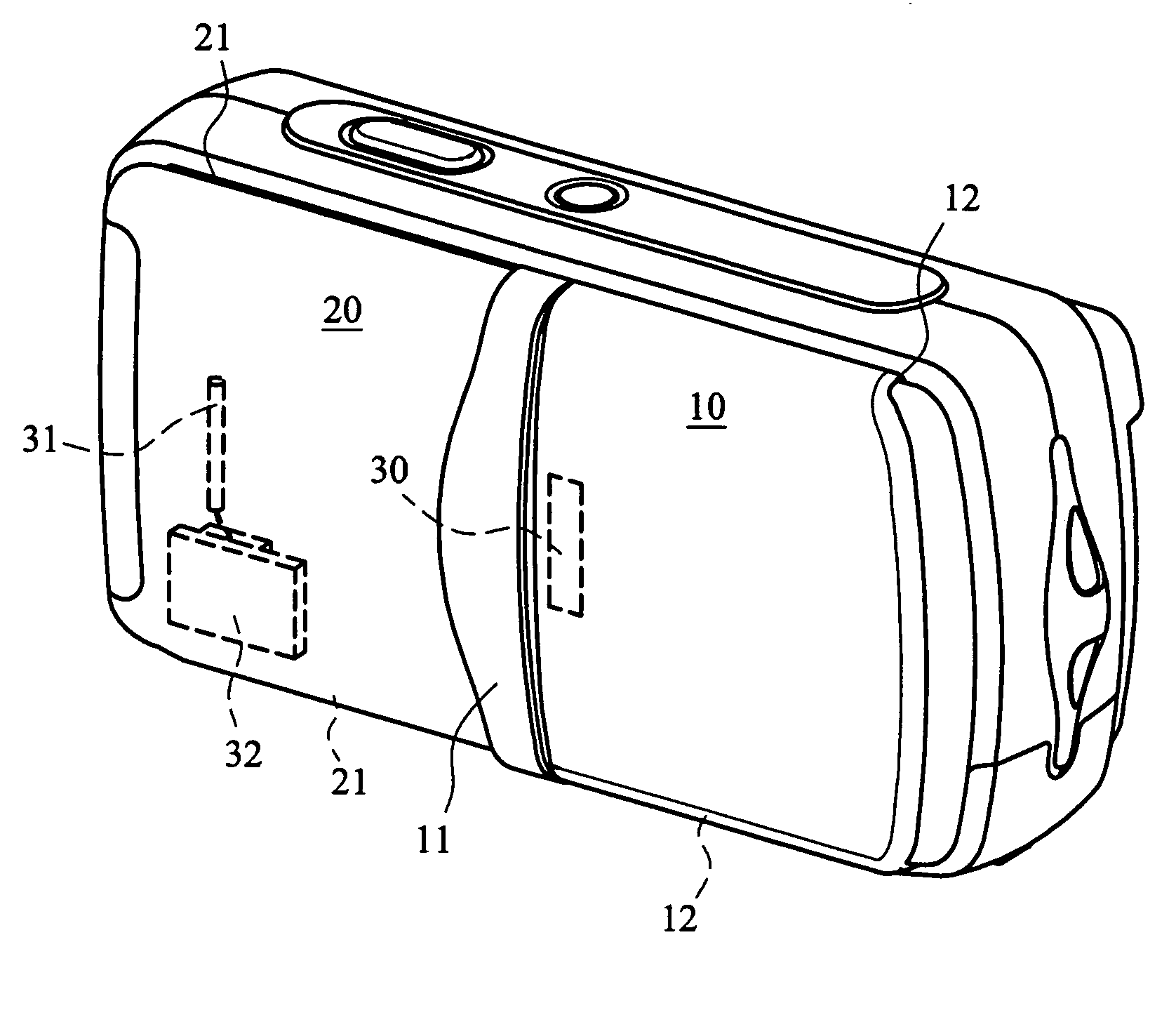
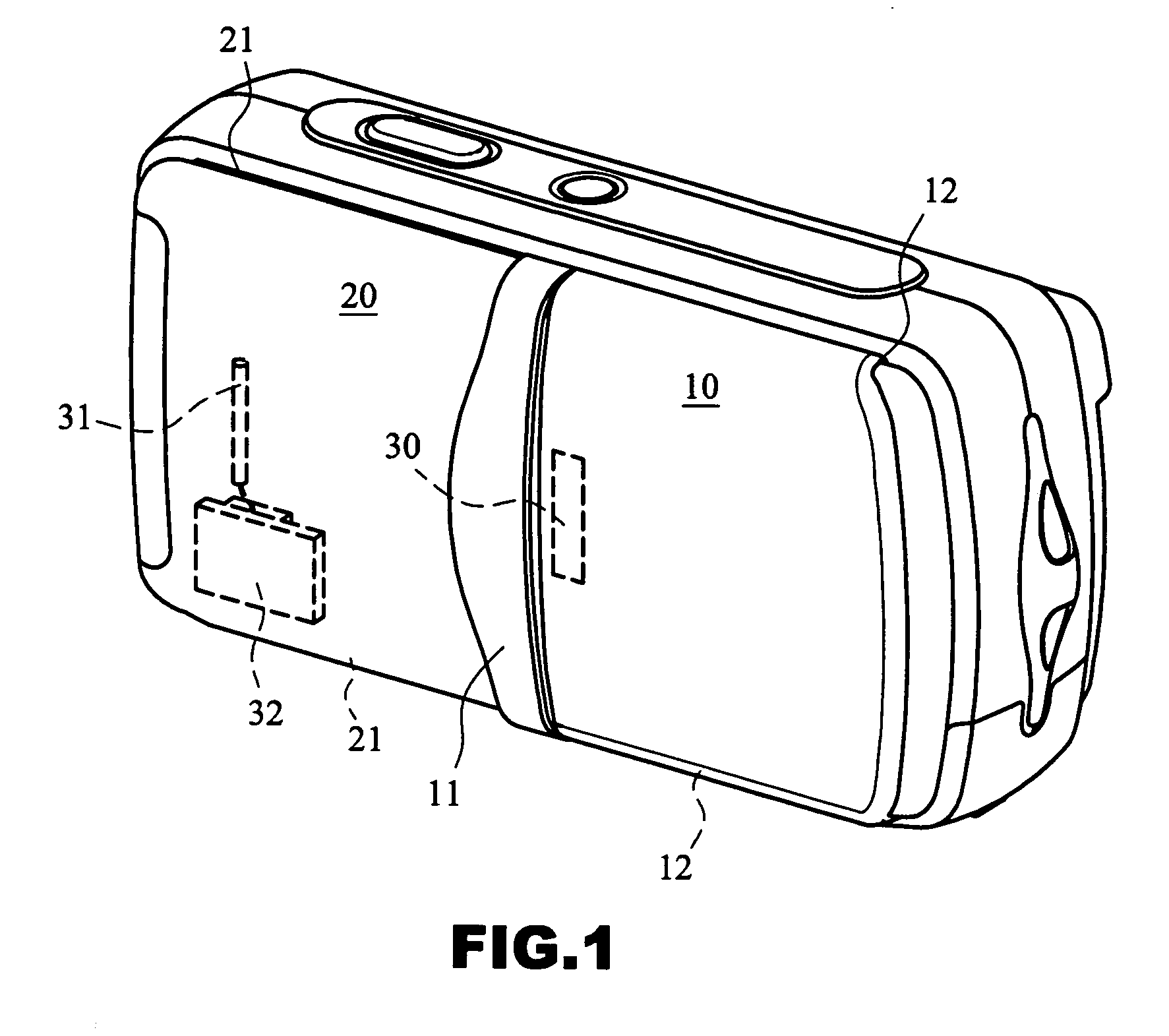
[0017] First of all, referring to FIG. 1, an embodiment of sliding cover (10) according to the present invention is slideably connected to the front shell (20) of the camera. The front shell (20) has a pair of sliding slots (21) used to slideably engaged with hook flanges (12) of the sliding cover (10), the inner surface of the front shell (20) is installed with a magnetic induction switch (31) connected with a printed circuit board (32) for switching the power of camera. A permanent magnet (30) is fixed on the sliding cover (10), for instance, hidden or embedded within the sliding cover (10). When the sliding cover (10) is slid to expose the camera lens, the permanent magnet (30) will close to the inductive range of the magnetic induction switch (31) to turn on the power circuit.

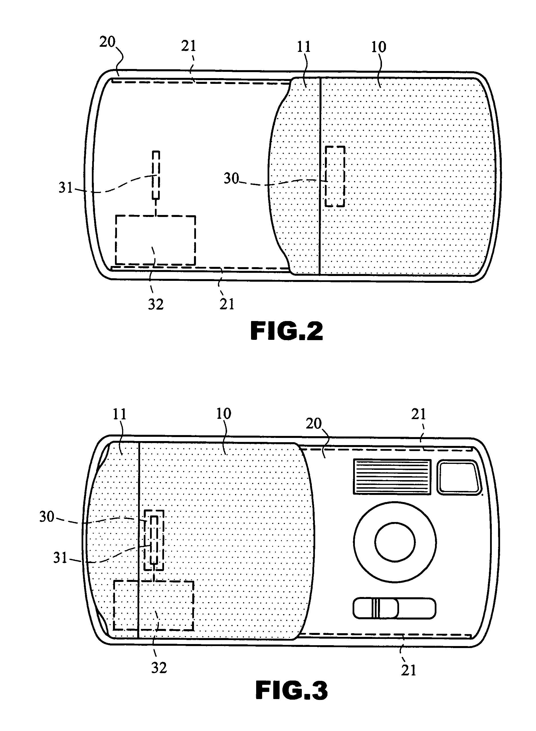
[0018] Referring to FIGS. 2 and 3. To improve the convenience for the camera users, the sliding cover (10) may further to comprise a push element (11) formed as a protrusion on the side of the sliding cove...


PUM


Abstract

A sliding cover for protecting camera lens and switching the power of the camera, comprising a cover plate and a permanent magnet. The cover plate is slideably connected with the front shell of the camera, a magnetic induction switch is installed at the inner side of the front shell. Furthermore, the permanent magnet is connected to the cover plate, when the lens is exposed while the cover plate is sliding away, the permanent magnet will then be close to the inducible switch and switch the power automatically. For sliding smooth, a few pads with low friction coefficient and wear-resistant property can be installed between the cover plate and the front shell of the camera; preferably, the inner side of the of the cover plate can further installed a rolling wheel to smooth the sliding and prevent scratch on the front shell surface when been highly pressed.

Description

FIELD OF THE INVENTION [0001] The present invention relates to a cover structure for protecting camera lens; and, more specifically, to a sliding cover which can switch power without real contact. BACKGROUND OF THE INVENTION [0002] Although most of the sliding covers are installed for protecting camera lens, there are diversities of structural innovation created one after another by manufacturers; for instance, U.S. Pat. No. 4,557,574, U.S. Pat. No. 6,257,776, U.S. Pat. No. 6,264,378, U.S. Pat. No. 6,322,259 and U.S. Pat. No. 6,491,448, the cover is a box-like cover plate, is connected to the equipment body. When taking the pictures, the user can telescopically slide the box-like cover plate to reveal the lens. The box-like cover plate can further be equipped with some operation buttons or components such as flash light, connected to the PCB inside the camera through flexible PCB or cable. The structure is complicated and the assembly is difficult. [0003] Other patent related slidin...

Claims


Application Information

Patent Timeline
Patent Type & Authority Applications(United States)
IPC IPC(8): G03B17/02
CPCG03B17/02
Inventor CHEN, YI YUAN
Owner HON HAI PRECISION IND CO LTD
Why Eureka
Try Eureka