Capillary tube printing tips for microarray printing

a printing tip and microarray technology, applied in the field of capillary tube printing tips for microarray printing, can solve the problems of difficult cleaning of quill pins, large amount of data, and insufficient control of chip manufacturing process, so as to achieve easy modification, simple printing tip, and minimal drop-to-drop variation

Inactive Publication Date: 2006-03-16
VANDERBILT UNIV
View PDF20 Cites 17 Cited by
  • Summary
  • Abstract
  • Description
  • Claims
  • Application Information

AI Technical Summary

Benefits of technology

[0015] The invention provides a simple printing tip. Tip loading is achieved by surface forces and capillary action. Pin delivery is achieved by touching the tip to the surface of a microarray printing substrate. One important aspect of the design is the flatness of the tip. This can be achieved on a glass tip by using an optical fiber polisher. A single load can be dispensed without reloading onto many consecutive substrate surfaces. In addition, drop-to-drop variation is minimal. Unlike quill pins, the volume transferred to the surface equilibrates very rapidly making the deposition characteristics time independent. The simplicity of the design also suggests that pin-to-pin variation will be insignificant. The tip design can be easily modified to deliver drops over a range of sizes and volumes. These tips may be produced at low cost so that they may be discarded between samples. This will obviate the need for a wash cycle and eliminate cross contamination issues.

Problems solved by technology

Significant variability across DNA microarrays is often observed and as a result typical DNA microarray hybridization results often discard much of the data.
One of the reasons for this is inadequate control of the chip manufacturing process.
Quill pins are more difficult to clean and are not as consistent as solid pins because the delicate design of the quill pin geometry makes them susceptible to deformation.
Their primary drawback is slow deposition speed because they must be reloaded before printing each spot.
Evaporation from the sample plates during lengthy print runs can also be a problem.
Their main drawback is difficulty in cleaning and reloading.
Typical ink jets are not designed for multiple samples so each unique probe solution would require its own ink jet device; a serious drawback for large arrays.
Residual sample after printing is typically not returned to the sample well.

Method used


Image

  • Capillary tube printing tips for microarray printing
  • Capillary tube printing tips for microarray printing
  • Capillary tube printing tips for microarray printing

Examples


first embodiment

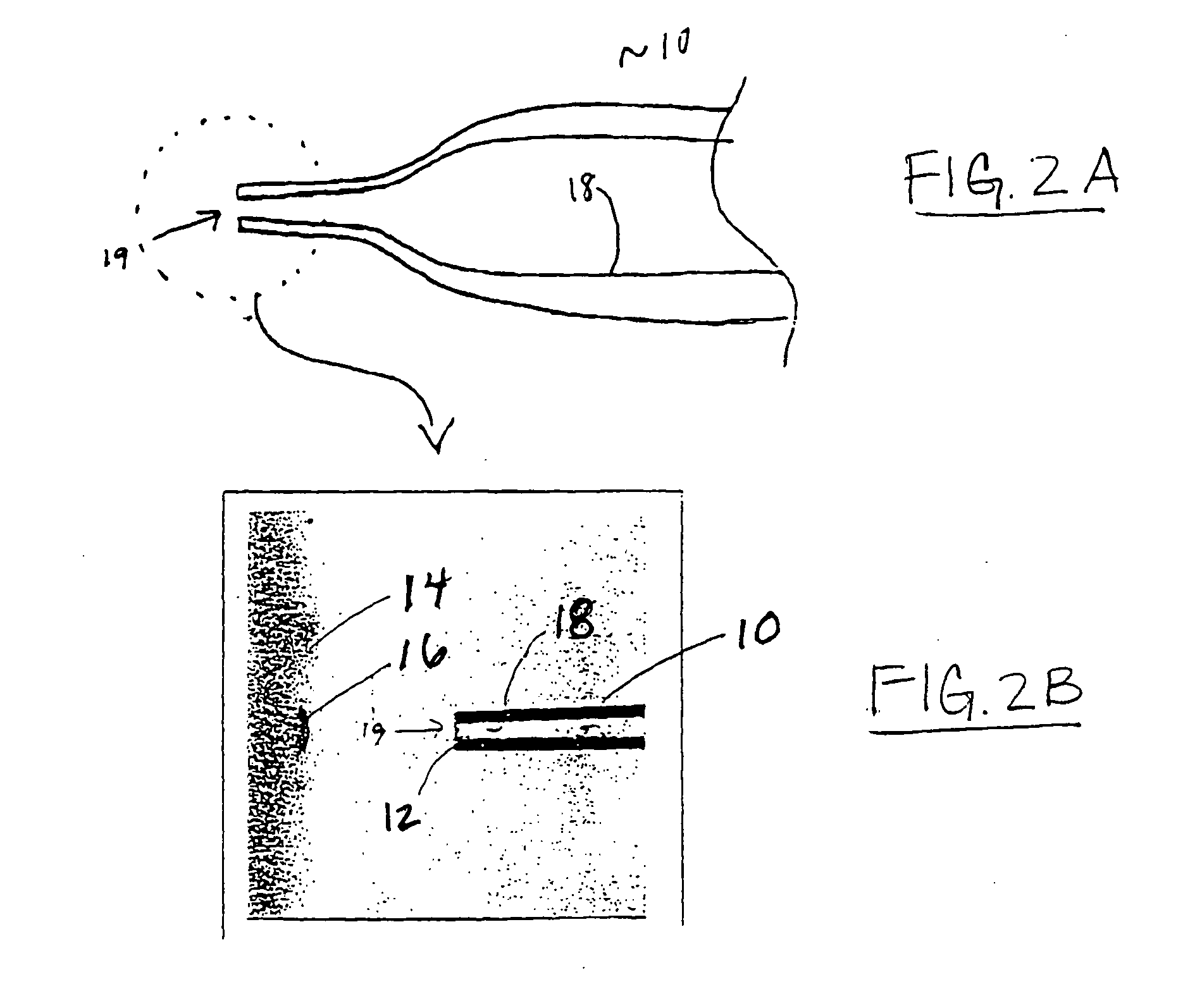
[0028] In FIGS. 2(a) and 2(b), a microarray printing tip in accordance with the present invention is illustrated. The tip is constructed as a capillary tube 10 having an inner bore 18. The inner bore 18 has an opening 19 at the distal (contact) end of the tube 10. An annular contact surface 12 surrounds the opening 19. The inner bore 18 has an inner diameter and an axial length that define a liquid reservoir volume which, in cooperation with capillary and surface forces applied at the interface between the liquid material and the inner surface of the inner bore, allows the tube 10 to receive and retain an appropriate amount of the liquid material.

[0029] As seen in FIG. 2(a), the diameter of the tube 10 and inner bore 18 increases from the distal (contact or printing) end (FIG. 2(b)) to the proximal (reservoir) end to provide a desired gradient in surface forces applied to the liquid material. As will be understood by those skilled in the art, the capillary forces holding the liquid ...

second embodiment

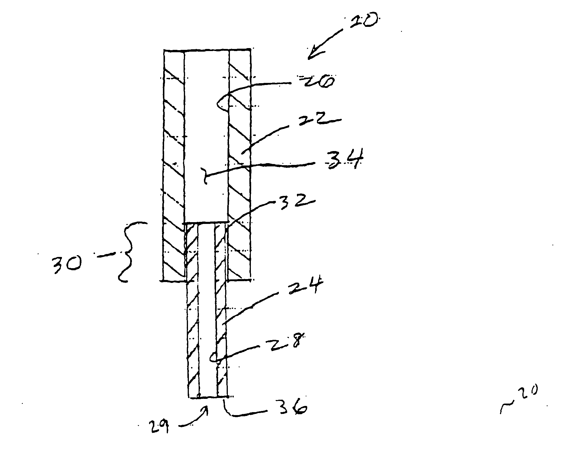
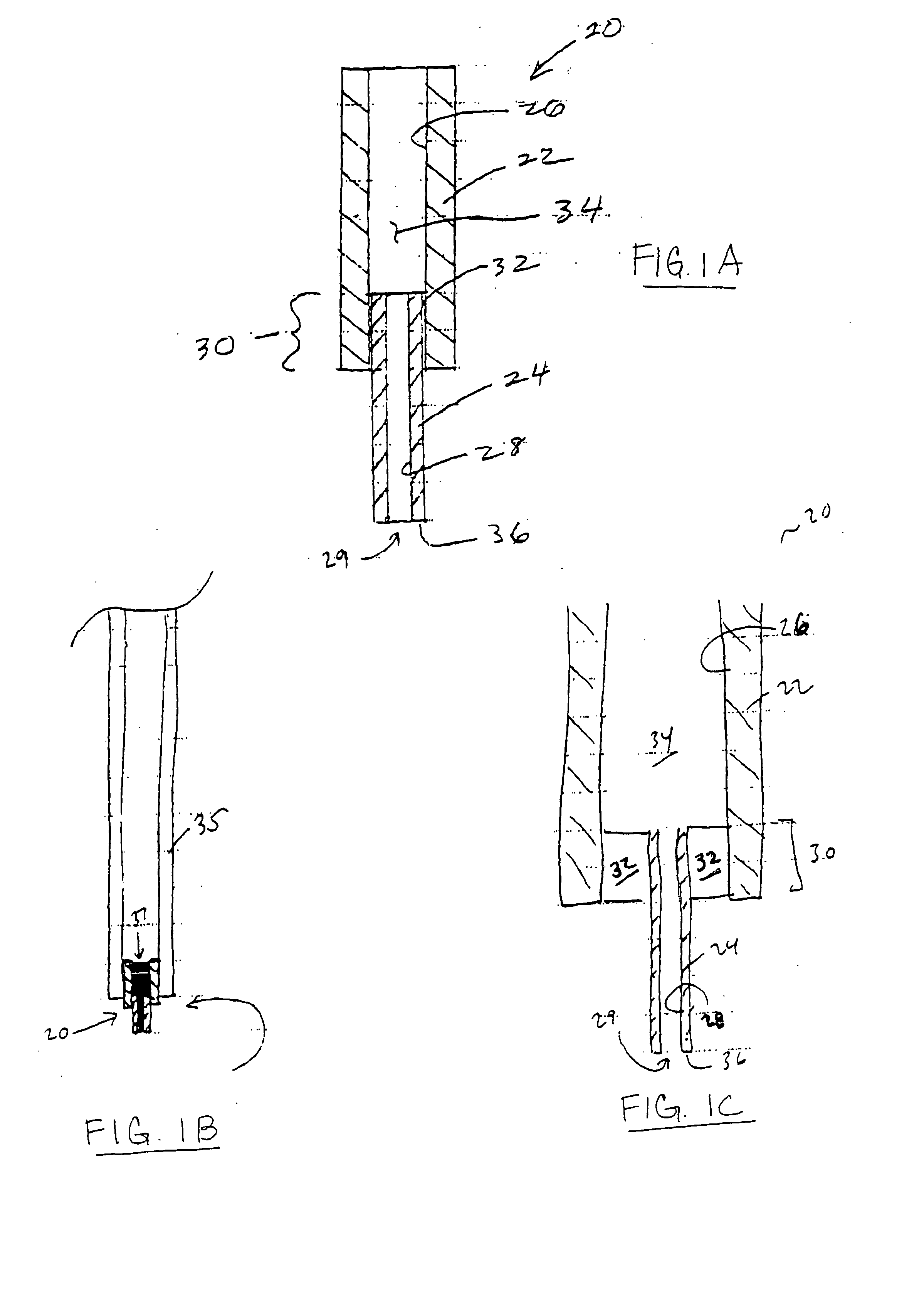
[0031]FIG. 1(a) shows a microarray printing tip 20 constructed from concentric first and second capillary tubes 24 and 22. The second capillary tube 22 (reservoir tube) has an inner bore 26 defining a liquid reservoir 34. The inner diameter of the inner bore 26 is larger than the outer diameter of the first capillary tube 24 so that the second capillary tube 22 partially overlaps (at region 30) the proximal end of the first capillary tube 24.

[0032] The first capillary tube 24 (printing tube) has an inner bore 28 in fluid communication with the inner bore 26 of the second capillary tube 22. The inner bore 28 has a bore opening 29 at the distal end of first tube 24. An annular contact surface 36, preferably flat, is formed at the distal end of the first capillary tube 24. The contact surface 36 surrounds the opening 29 from the inner bore 28 of the first capillary tube 24.

[0033] The axial length and inner diameter of the inner bore 26 of the second capillary tube 22, in cooperation w...

third embodiment

[0038]FIG. 3 shows a capillary tube printing tip in accordance with the present invention, constructed from a single glass capillary tube 40 having an inner bore 42 of uniform geometry. The distal (contact) end of tube 40 has a contact surface 52 surrounding the bore opening 50. The inner bore 42 is sized and shaped to receive and retain by capillary force an effective deposition volume of the liquid material. Similarly, the contact surface 52 and bore opening 50 are adapted for depositing a drop of the liquid material when the contact surface 52 is moved proximate the printing substrate. A key design feature of using two capillary tubes as shown in the embodiment of FIGS. 1(a)-1(c) is the ability to modulate the relative strength of surface forces between the printing and reservoir capillary tubes. This functionality can also be attained by using a hydrophilic surface treatment to provide a gradient in surface forces along regions of a single capillary tube. Thus, applying a surfac...


PUM


Abstract

A microarray contact printing is formed from at least one capillary tube. The tip has concentric reservoir and printing capillary tubes, with a first capillary tube (24) and a second capillary tube (22) having an inner bore (26) with an inner diameter larger than an outer diameter of the first capillar tube (24) so that the second capillary tube (22) partially overlaps a proximal end of the first capillary tube (24). The first capillary tube (24) has a contact surface (36) at a distal end. The inner bore of the first capillary tube (24) is adapted for drawing the printing solution retained in the second capillary tube (22) and depositing a drop of a solution on a printing substrate when the contact surface (36) is moved proximate the substrate.

Description

[0001] A portion of the disclosure of this patent document contains material that is subject to copyright protection. The copyright owner has no objection to the facsimile reproduction by anyone of the patent document or the patent disclosure, as it appears in the Patent and Trademark office patent file or records, but otherwise reserves all copyright rights whatsoever. TECHNICAL FIELD [0002] The present invention relates generally to devices and methods used for microarray printing. More particularly, this invention pertains to printing tips used for depositing spots of liquid material across a microarray printing substrate. BACKGROUND ART [0003] DNA microarrays and other massively parallel screening technologies are redefining the approach to discovery in biomedical research. One key aspect to interpreting these parallel screening approaches is the uniformity of conditions across the probe screen. Significant variability across DNA microarrays is often observed and as a result typ...

Claims


Application Information

Patent Timeline
Patent Type & Authority Applications(United States)
IPC IPC(8): B01L3/02B01J19/00
CPCB01J19/0046B01L2400/0406B01J2219/00387B01J2219/00576B01J2219/00585B01J2219/00596B01J2219/00605B01J2219/00612B01J2219/00659B01J2219/00677B01J2219/00691B01J2219/00722B01L3/0241B01L3/0262B01L2300/0838B01L2300/161B01L2300/165B01L2400/022B01J2219/00367
Inventor HASELTON, FREDERICKRMCQUAIN, MARKK
Owner VANDERBILT UNIV
Why Eureka
Try Eureka