Focused ultrasound system for surrounding a body tissue mass

a focused ultrasound and tissue technology, applied in the field of focused ultrasound systems, can solve the problems of acoustic beams not reaching the target tissue, acoustic beams may impinge on the tissue, and non-target tissue damage at the near field and/or the far field,

Active Publication Date: 2006-03-16
INSIGHTEC
View PDF99 Cites 318 Cited by
  • Summary
  • Abstract
  • Description
  • Claims
  • Application Information

AI Technical Summary

Benefits of technology

[0007] In yet another embodiment, a method of treating body tissue with ultrasound energy includes positioning a part of the body containing the tissue to be treated within an aperture defined by a transducer device, the transducer device having a plurality of acoustic transducer elements positioned in a formation about the aperture, and providing drive signals to cause one or more of the transducer elements to emit acoustic energy focused in one or more focal zones in the tissue to be treated.

Problems solved by technology

These areas have a high absorption coefficient compared to regular tissue, thereby risking damage to non targeted tissue at the near field and / or the far field.
Also, in some cases, the acoustic beam may impinge on a tissue (e.g., bone tissue) that would not allow the beam to pass through by reflecting and / or absorbing most of the impinging energy.
As a result, the acoustic beam may not reach the target tissue, and may generate undesired heating at the tissue surface that is blocking or interfering the acoustic beam.
In some cases, the heating of bone tissue may also heat, and adversely affect, a nerve that is adjacent the bone tissue.
Certain physical anatomy, e.g., a breast or an arm, can impose special problems in positioning an ultrasound transducer to effectively direct the ultrasound energy at the target tissue mass (e.g., a tumor underlying a nipple, or along one side of a bone), while reducing the risk of adversely impacting nearby healthy tissue.

Method used


Image

  • Focused ultrasound system for surrounding a body tissue mass
  • Focused ultrasound system for surrounding a body tissue mass
  • Focused ultrasound system for surrounding a body tissue mass

Examples


Embodiment Construction

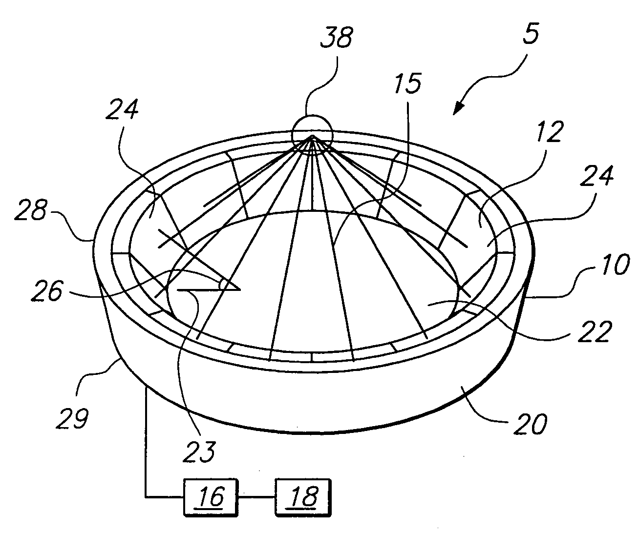
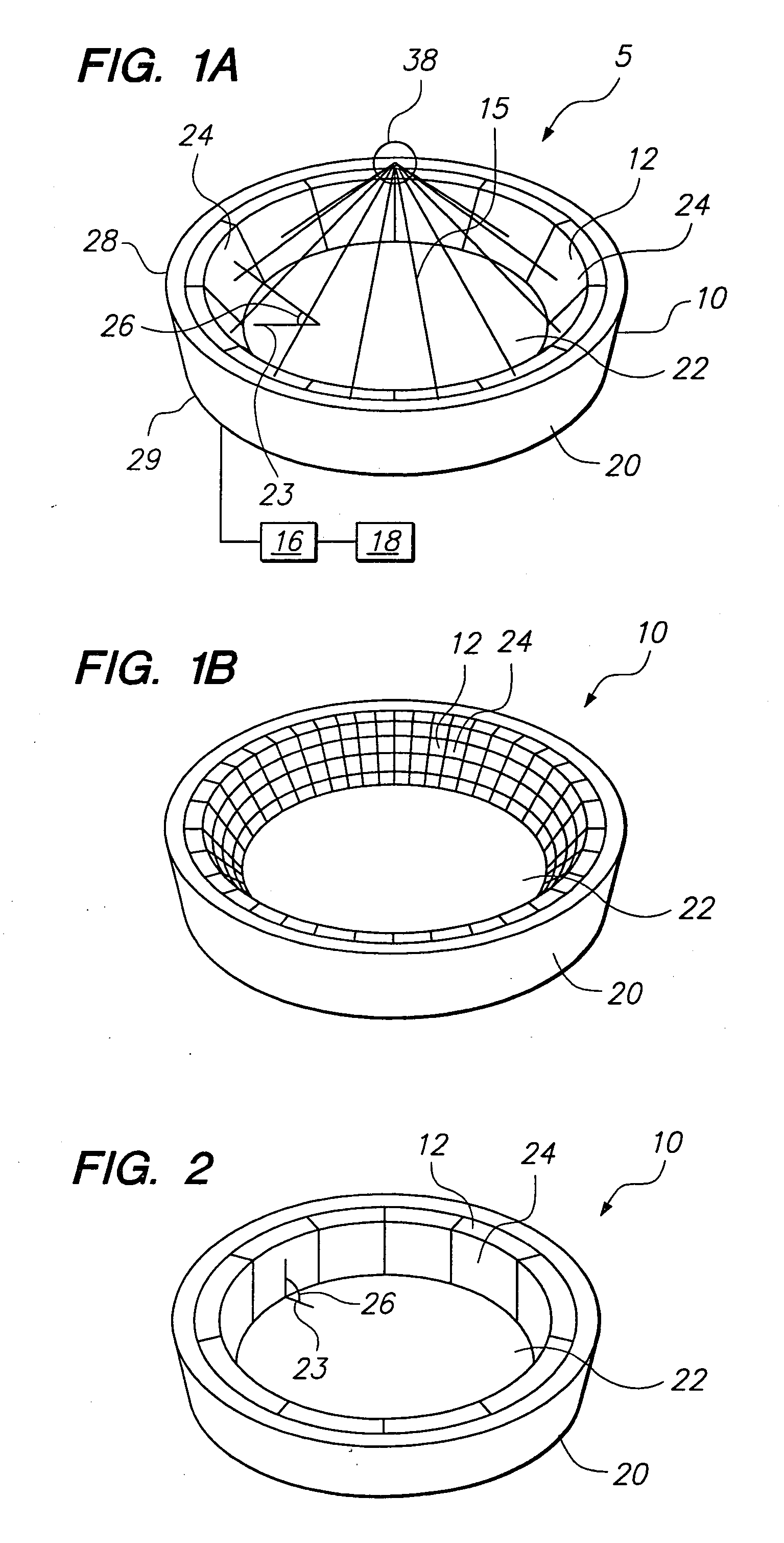
[0020]FIG. 1 illustrates a focused ultrasound system 5 that includes a transducer device 10 constructed in accordance with some embodiments of the invention. The focused ultrasound system 5 includes a drive circuitry 16 coupled to the transducer device 10, and a controller 18 coupled to the drive circuitry 16. The transducer device 10 is configured to deliver acoustic energy (represented by beam 15) to a target tissue region located inside a patient. The acoustic energy 15 may be used to coagulate, necrose, heat, or otherwise treat the target tissue region, which may be a benign or malignant tumor within an organ or other tissue structure (not shown).

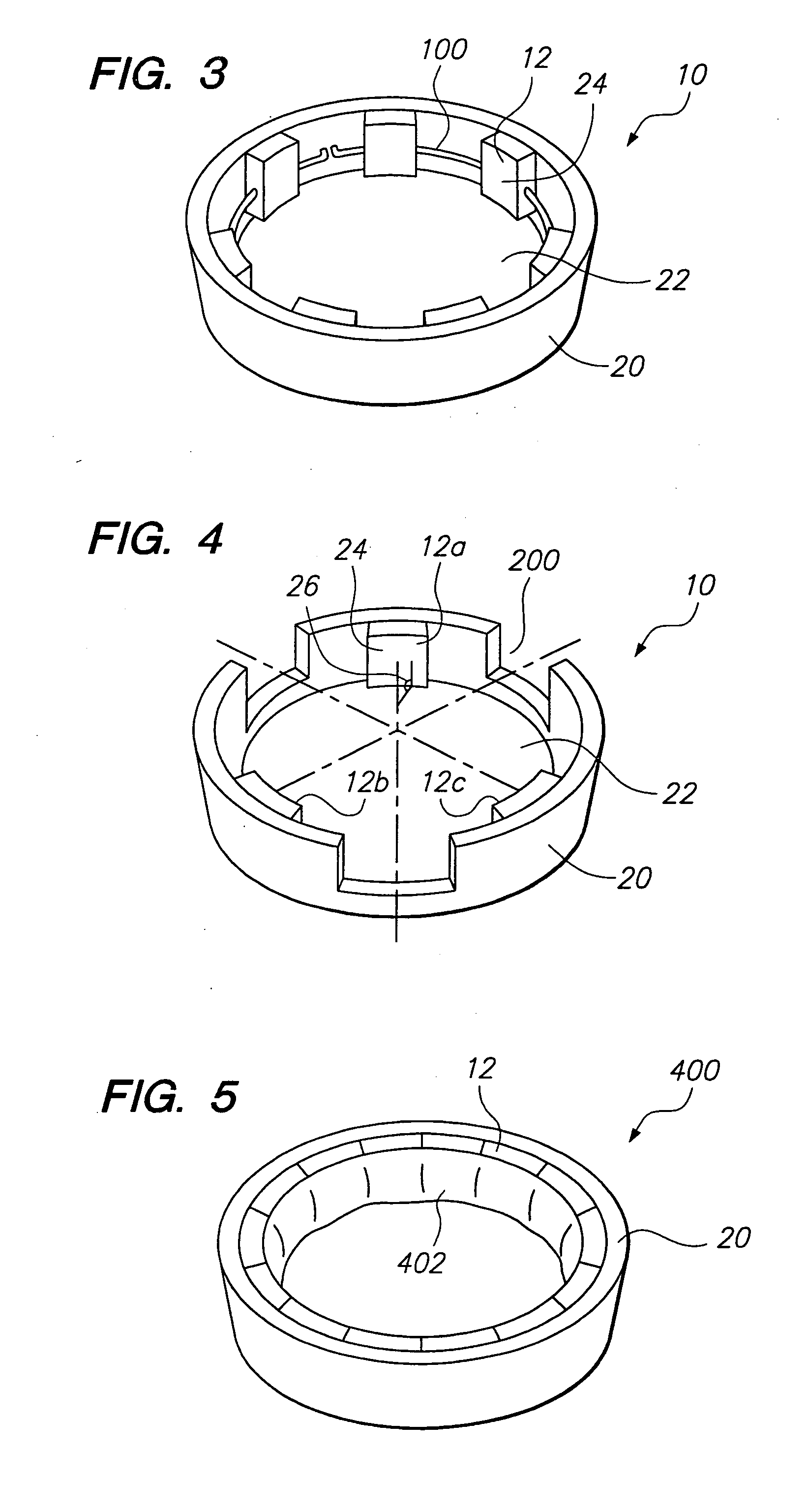
[0021] In the illustrated embodiments, the transducer device 10 includes a structure 20 and a plurality of transducer elements 12 secured to the structure 20. The transducer elements 12 are positioned in an arrangement or formation to thereby define an opening22. During use, the opening 22 allows at least a portion of an object, such a...


PUM


Abstract

A focused ultrasound system includes an ultrasound transducer device forming an opening, and having a plurality of transducer elements positioned at least partially around the opening. A focused ultrasound system includes a structure having a first end for allowing an object to be inserted and a second end for allowing the object to exit, and a plurality of transducer elements coupled to the structure, the transducer elements located relative to each other in a formation that at least partially define an opening, wherein the transducer elements are configured to emit acoustic energy that converges at a focal zone.

Description

FIELD OF INVENTION [0001] The present invention relates generally to apparatus and methods for delivering diagnostic and / or therapeutic ultrasound energy from a transducer disposed outside a body. BACKGROUND [0002] Devices and systems using acoustic energy, particularly within the ultrasonic range, i.e., acoustic waves with a frequency greater than about twenty kilohertz (20 kHz), and more typically between fifty kiloHertz and ten MegaHertz (0.05-10 MHz), have been used to diagnose and treat patients. Ultrasonic energy may be employed to obtain images of a patient during a diagnostic or therapeutic procedure. In addition, ultrasound systems have been used for treating tissue, e.g., by directing acoustic energy towards a target tissue region within a patient, such as a cancerous or benign tumor, to coagulate, necrose, generate mechanical damage (by cavitation) or otherwise heat the tissue region. For example, one or more piezoelectric transducers may be disposed adjacent a patient's ...

Claims


Application Information

Patent Timeline
Patent Type & Authority Applications(United States)
IPC IPC(8): A61B8/14
CPCA61B8/0825A61B8/4281A61B8/4483A61B8/0808A61N2007/0078B06B1/0633A61N7/02A61B8/4494
Inventor VITEK, SHUKIVORTMAN, KOBI
Owner INSIGHTEC
Why Eureka
Try Eureka