
Communication control device for passenger protection device

a communication control device and protection device technology, applied in the direction of electric devices, process and machine control, navigation instruments, etc., can solve the problems of constant noise generation, unfavorable transmission, and over-all communication control devices that consume considerable power, so as to reduce power consumption and unwanted noise

Inactive Publication Date: 2006-03-16
KEIHIN CORP
View PDF16 Cites 4 Cited by
  • Summary
  • Abstract
  • Description
  • Claims
  • Application Information

AI Technical Summary

Benefits of technology

[0009] It is an object of the present invention to provide a communication control device for passenger protection device which can reduce power consumption and unwanted noise, and can determine that a sensor has ceased to function without the provision of a separate determination unit.
[0011] Although impact against the vehicle must be constantly measured so that the passenger protection device can activate reliably when the vehicle collides, heavy impacts against the vehicle are extremely infrequent. Accordingly, the controller fitted to the satellite sensor unit sets a reference value range beforehand, and, when a measurement or a calculated value obtained from a signal which detects an impact is within the reference value range, communications from the satellite sensor unit to the ECU are transmitted at an interval which is longer than the predetermined time interval. This reduces the frequency of communications from the satellite sensor unit to the ECU.
[0016] When the measurement or the calculated value is within the reference value range, communications from the satellite sensor unit to the ECU are transmitted at an interval which is longer than the predetermined time interval. Here, when a malfunction is detected in the satellite sensor unit, communications are transmitted from the satellite sensor unit to the ECU at the predetermined time interval. Consequently, an irregular state is reached wherein the communication is transmitted at the predetermined time interval in spite of that fact that the measurement is within the reference value range, making it possible to determine that the satellite sensor unit has malfunctioned.
[0017] According to the communication control device for passenger protection device of this invention, the frequency of communications from the satellite sensor unit to the ECU is reduced by transmitting the communications at an interval which is longer than a predetermined time interval. This makes it possible to reduce power consumption and unwanted noise.
[0019] According to the communication control device for passenger protection device of this invention, even if a measurement which is momentarily within the reference value range once again exceeds the reference value range during the predetermined time, the frequency of communications from the satellite sensor unit to the ECU remains stable. Therefore, the passenger protection device can be reliably controlled during the predetermined time.

Problems solved by technology

In this type of communication control device for passenger protection device, since digital signals are constantly transmitted from the satellite sensors to the main controller, the overall communication control device consumes considerable power, and noise is constantly generated by the transmitted output signals.
In the communication control device for passenger protection device disclosed in the above Patent Literature, when the output of the detected value or the calculated value from a satellite sensor is zero, the communication control device for passenger protection device cannot determine whether: (a) the output has been determined to be less than a predetermined value with respect to the threshold for determining collision whereby output is prohibited, or (b) there is a malfunction in the satellite sensor itself, making transmission impossible.
Although impact against the vehicle must be constantly measured so that the passenger protection device can activate reliably when the vehicle collides, heavy impacts against the vehicle are extremely infrequent.

Method used


Image

  • Communication control device for passenger protection device
  • Communication control device for passenger protection device
  • Communication control device for passenger protection device

Examples


Embodiment Construction

[0028] In the following, an embodiment of the present invention will be explained with reference to the drawings.

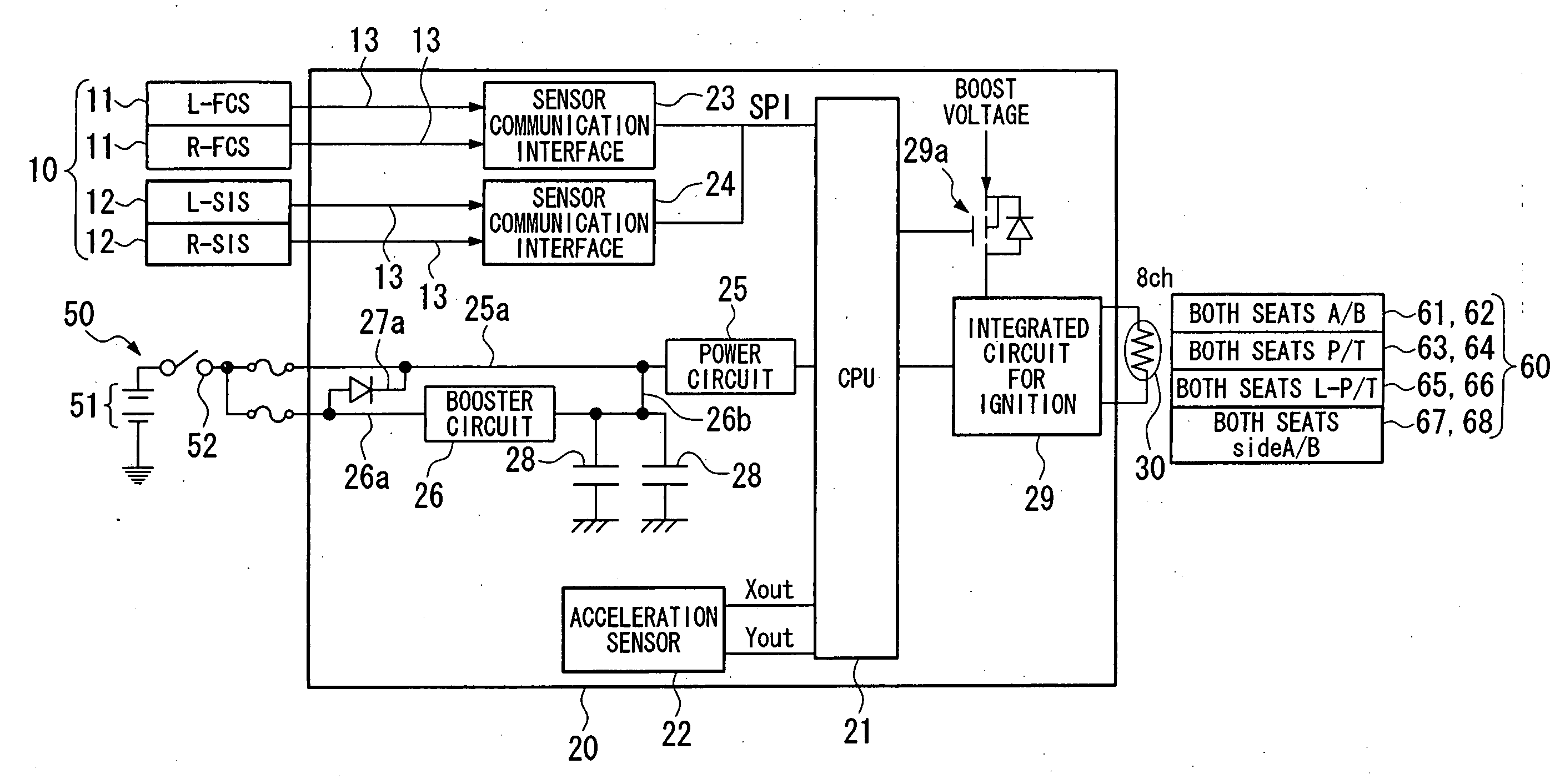
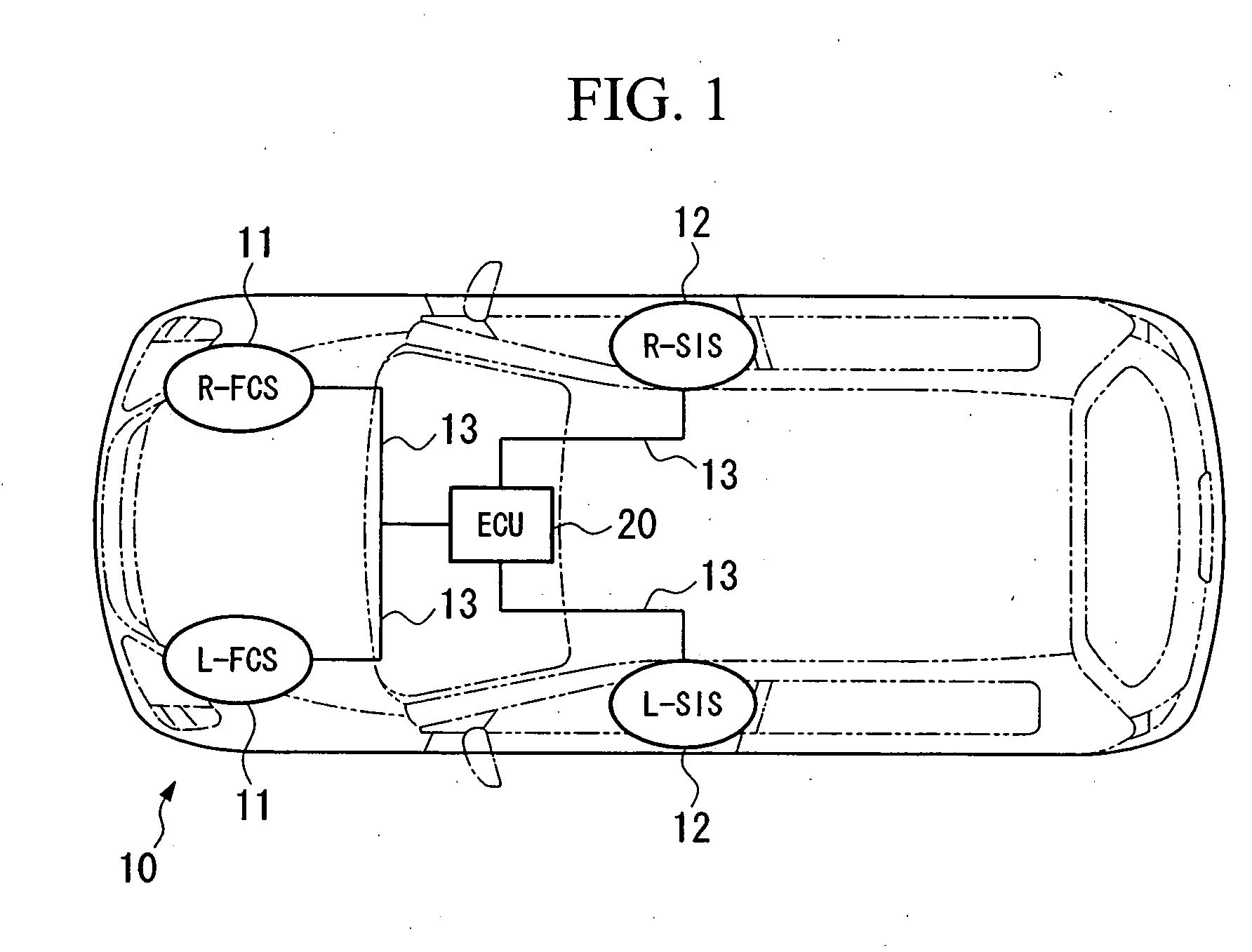
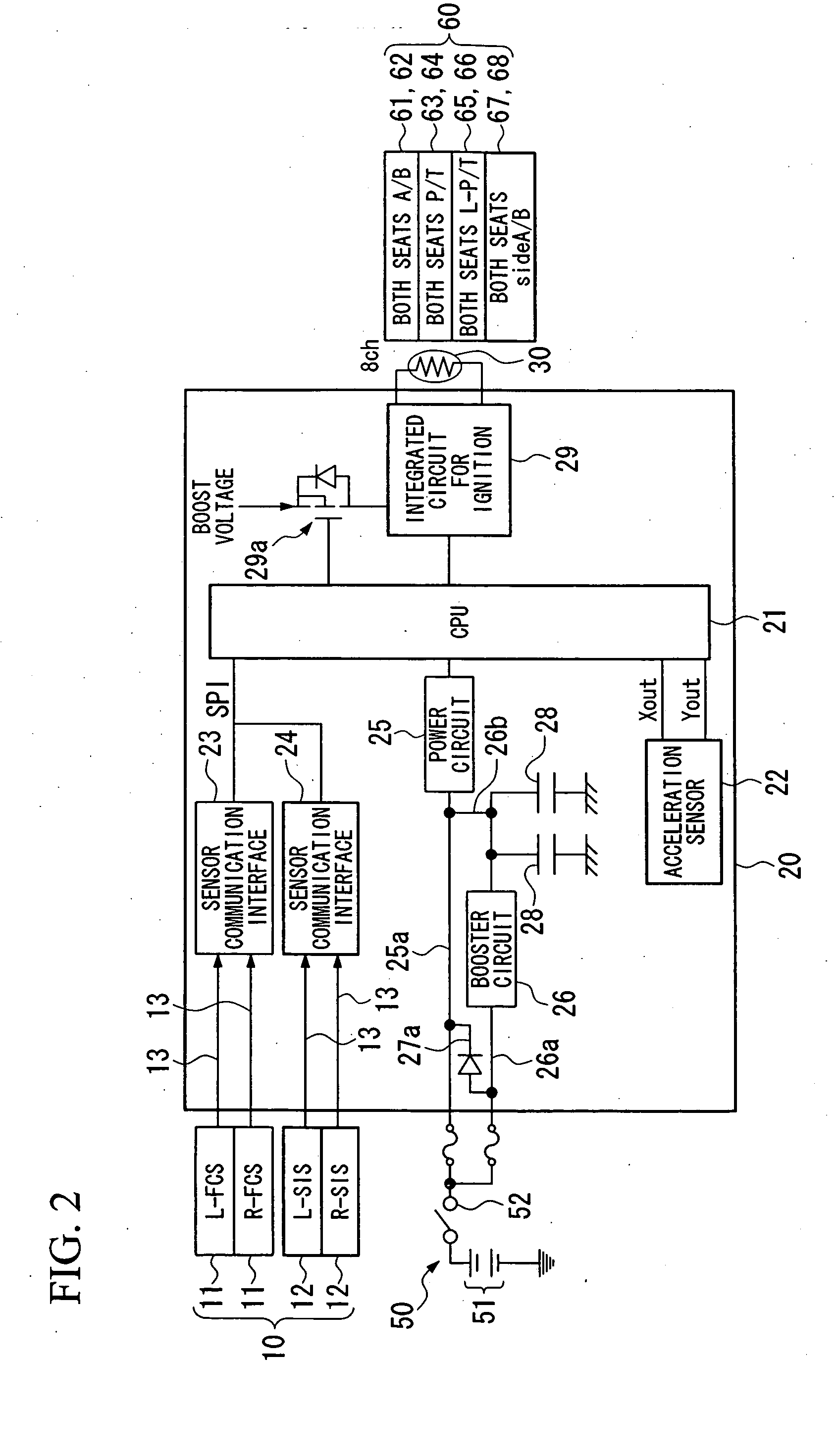
[0029]FIG. 1 is a schematic layout of a communication control device for passenger device which is an embodiment of the present invention. The communication control device for passenger protection device is mounted on a vehicle 1, and includes a satellite sensor unit 10 and an ECU 20. The satellite sensor unit 10 consists of front crash sensors (L-FCS and R-FCS) 11 and side impact sensors (L-SIS and R-SIS) 12.

[0030] The front crash sensors 11 are installed at predetermined positions on the vehicle 1, namely at both sides of the frontmost section of the vehicle 1. The side impact sensors 12 are installed at predetermined positions on the vehicle 1, namely on the left and right sides of the vehicle 1.

[0031] The ECU 20 is installed at a different position to the satellite sensor unit 10, namely at the center of the vehicle 1. The ECU 20 is connected to the front crash sen...


PUM


Abstract

A communication control device for passenger protection device includes a satellite sensor unit and an ECU being connected to the satellite sensor unit via a communication line. The satellite sensor unit includes a satellite sensor main body, which detects an impact against a vehicle, and a controller, which obtains a measurement from a signal detected by the satellite sensor main body. The ECU includes a main controller which determines deployment of a passenger protection device. The controller of the satellite sensor unit is adapted to compares the measurement or a calculated value which is calculated based on the measurement with a preset reference value range, and, when the measurement or the calculated value is within the reference value range, the controller transmits a communication from the satellite sensor unit to the ECU at an interval which is longer than a predetermined time interval.

Description

BACKGROUND [0001] 1. Field of the Invention [0002] The present invention relates to a communication control device for passenger protection device, which is used as a supplemental restraint system (SRS) for protecting passengers when a vehicle collides. [0003] Priority is claimed on Japanese Patent Application No. 2004-266644, filed Sep. 14, 2004, the contents of which are incorporated herein by reference. [0004] 2. Description of the Related Art [0005] Conventionally, for example, a communication control device for passenger protection device includes, in a center unit, for example, a main controller provided near a center console, a floor sensor provided in a center of the vehicle, and a plurality of satellite sensors provided at the front and sides of the vehicle. The main controller determines a collision state of the vehicle based on signals which are output from the floor sensor and the satellite sensors, and controls the activation of airbags. [0006] The floor sensor is gener...

Claims


Application Information

Patent Timeline
Patent Type & Authority Applications(United States)
IPC IPC(8): E05F15/00
CPCB60R21/013B60R2021/01184B60R21/0132B60R21/0136
Inventor SEIKAI, HIROSHINARITA, SYOJIOZAWA, HIDEAKITAKAHASHI, MASAAKI
Owner KEIHIN CORP
Learn More