Rotating drive module with position locking mechanism

Active Publication Date: 2006-03-23
PRECISION REMOTES
View PDF5 Cites 17 Cited by
  • Summary
  • Abstract
  • Description
  • Claims
  • Application Information

AI Technical Summary

Benefits of technology

[0009] The present invention is directed towards a mechanism for a fast rotating remotely controlled firearm device that can be precisely positioned. The inventive mechanism includes a circular gear that rotates about a base and two drive motors that are connected to worm (or p

Problems solved by technology

If the circular gear is not locked, the circular gear is able to rotate slightly about the base, reducing the aiming accuracy of the firearm.
This small amount of movement in a si

Method used


Image

  • Rotating drive module with position locking mechanism
  • Rotating drive module with position locking mechanism
  • Rotating drive module with position locking mechanism

Examples


Embodiment Construction

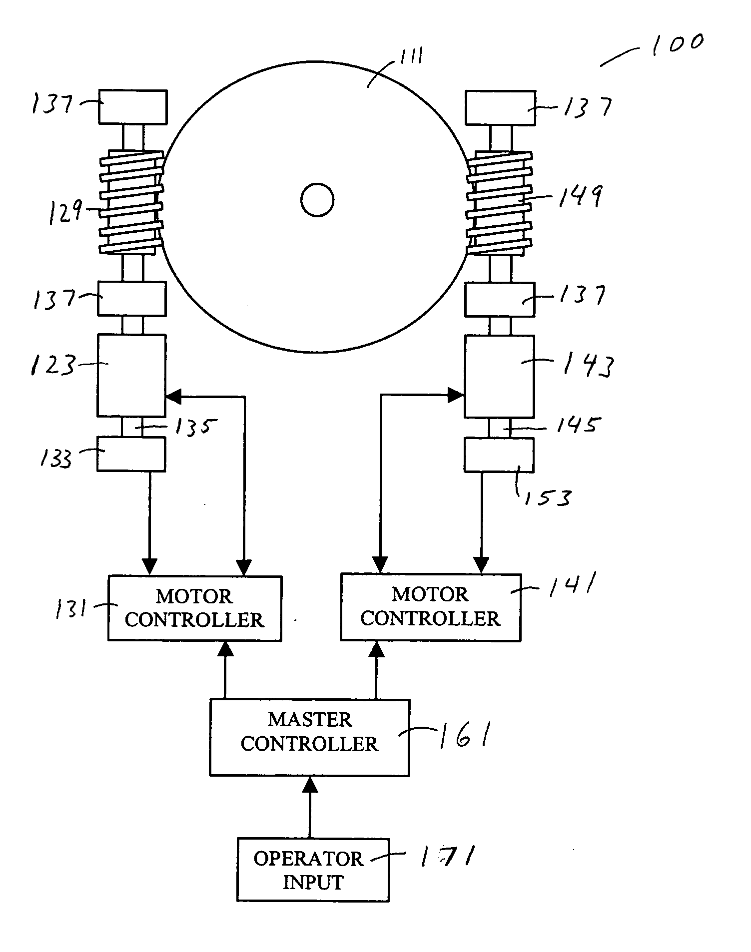
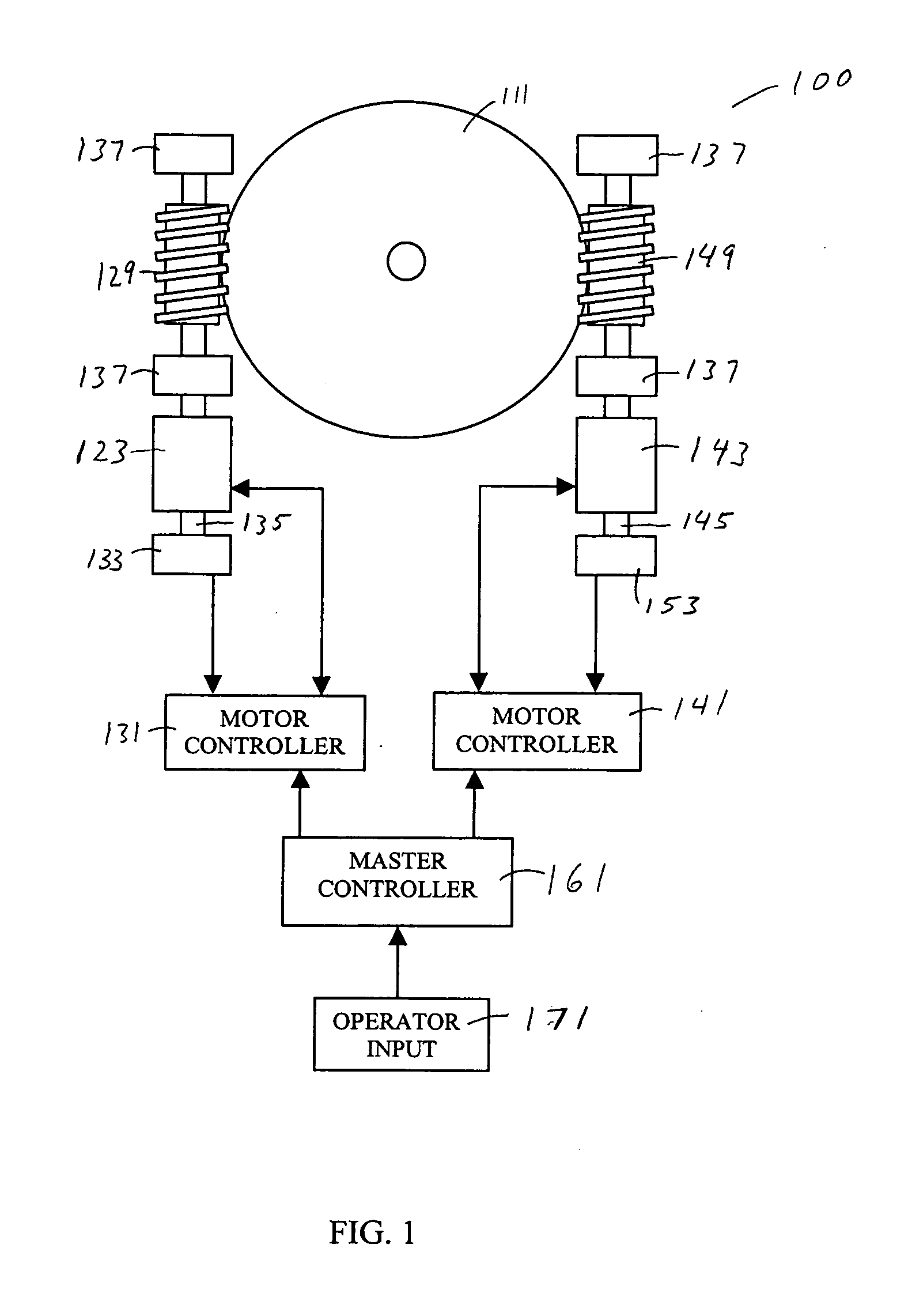
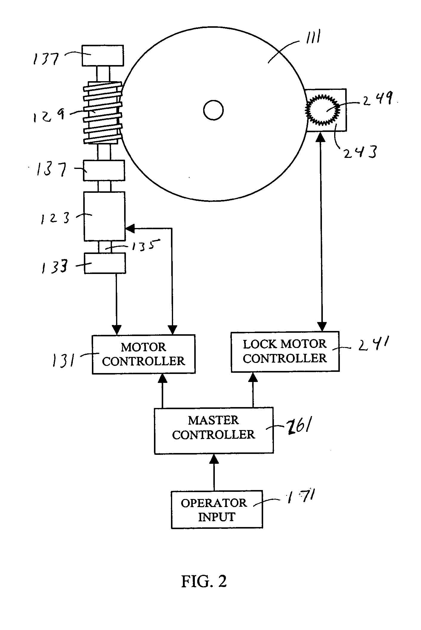
[0019] A rotating firearm platform includes a circular gear having teeth around its circumference and a motor connected to a worm (or alternatively a spur or pinion) gear that engages the circular gear teeth. The firearm is placed in a mount that is fastened to the circular gear. By rotating the worm gear, the circular gear and firearm also rotate. Although this single worm gear drive system is capable of rotating the firearm quickly, it cannot precisely and securely position the circular gear and therefore the firearm cannot be accurately aimed. The positioning accuracy problem is inherent with the single worm gear configuration because there is a certain amount of “play” between the helical worm gear and the teeth of the circular gear. The helical worm gear slides across the surfaces of the circular gear teeth and this play is required for the worm gear to rotate smoothly.

[0020] The problem is that the play prevents the circular gear from being accurately fixed in a position. Whe...


PUM


Abstract

A system used in a remotely controlled firearm device includes a circular gear and two worm gears. The worm gears engage the outer diameter of the circular gear and rotate synchronously to rotate the circular gear to align the firearm device with a target. Once the firearm device is aligned, the circular gear is locked into a fixed position that does not have any hysteresis by rotating the two worm gears asynchronously.

Description

CROSS-REFERENCE TO RELATED APPLICATIONS [0001] This application claims priority to U.S. Provisional Application No. 60 / 612,439 filed Sep. 22, 2004, which is hereby incorporated by reference.BACKGROUND [0002] Live fire remote units such as Precision Remote's Telepresent Rapid Aiming Platform (TRAP) provide remote control of firearms. Remotely controlled firearms are useful in keeping humans out of hostile environments while defending an area from attack. These units allow an operator to view a target through a video camera and operate the firearm from a remote location. [0003] The firearm is mounted to a base that rotates about a vertical axis. In order to aim the firearm, the base must be able to rotate through yaw control—also known as pan motion. The ideal characteristics for pan motion are: 1) fast slew rotational motion, 2) a wide range of movement up though 360 degrees and 3) extreme accuracy when the pan motion is stopped to properly aim the firearm. This would allow the firea...

Claims


Application Information

Patent Timeline
IPC IPC(8): F16H37/06
CPCF16H1/225F16H55/24F16H57/12Y10T74/1471Y10T74/19051Y10T74/19014F16H2057/122
Inventor HAWKES, GRAHAMHOBSON, ERIC
Owner PRECISION REMOTES
Why Eureka
Try Eureka