
Electric power steering system

a technology of electric power steering and steering gear, which is applied in the direction of electrical steering, mechanical equipment, transportation and packaging, etc., can solve the problems of affecting the steering feel and quietness of the passenger compartment, affecting the design, and the noise elimination or prevention effect of gear teeth may be deteriorated, so as to improve the steering feel of the vehicle, reduce the noise generated by the drive gear and the driven gear, and simple configuration

Inactive Publication Date: 2006-03-23
JTEKT CORP
View PDF11 Cites 10 Cited by
  • Summary
  • Abstract
  • Description
  • Claims
  • Application Information

AI Technical Summary

Benefits of technology

The invention is a solution to reduce gear teeth striking noise and meshing slide noise between the drive and driven gears in an electric power steering system. The invention uses a ring element that slides relative to the gear body, which attenuates the vibration of the gear body at an early stage, resulting in effective reduction of gear teeth striking noise and meshing slide noise. This simple construction replaces the elastic element used in the related art, improving the steering feel of the vehicle and realizing quietness in the passenger compartment.

Problems solved by technology

In the electric power steering system that is configured as has been described above, noise is generated at the time of steering when the vehicle is running on a road whose surface is rough or has irregularities, whereby the steering feel and the quietness in the passenger compartment are badly affected.
However, the elastic element repeats its compression and restoration such that the elastic element is elastically compressed at the position of the meshed portions of the first and second gears, whereas the elastic element is elastically restored at positions other than the meshed portions, whereby the elastic element is worn and fatigued earlier, triggering a risk that the gear teeth striking noise eliminating or preventing effect may be deteriorated earlier.
Furthermore, it is not easy from the view point of design to set the thickness of the elastic element that is to reside between the first and second gears and the hub, to set the hardness of the elastic element or to select a material for the elastic material with a view to obtaining the vibration suppressing effect.
In addition, it is difficult to install the elastic element between the first and second gear and the hub and hence it is difficult to manufacture the relevant electric power steering system, and the configuration thereof is such as to be difficult to attain the originally intended effect.

Method used


Image

  • Electric power steering system
  • Electric power steering system
  • Electric power steering system

Examples


Embodiment Construction

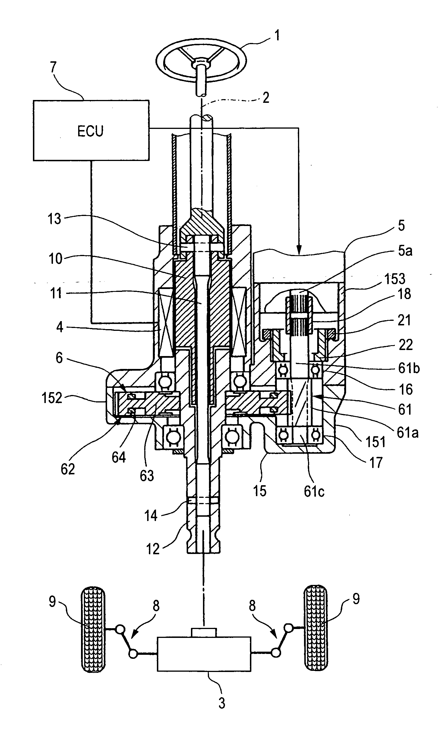
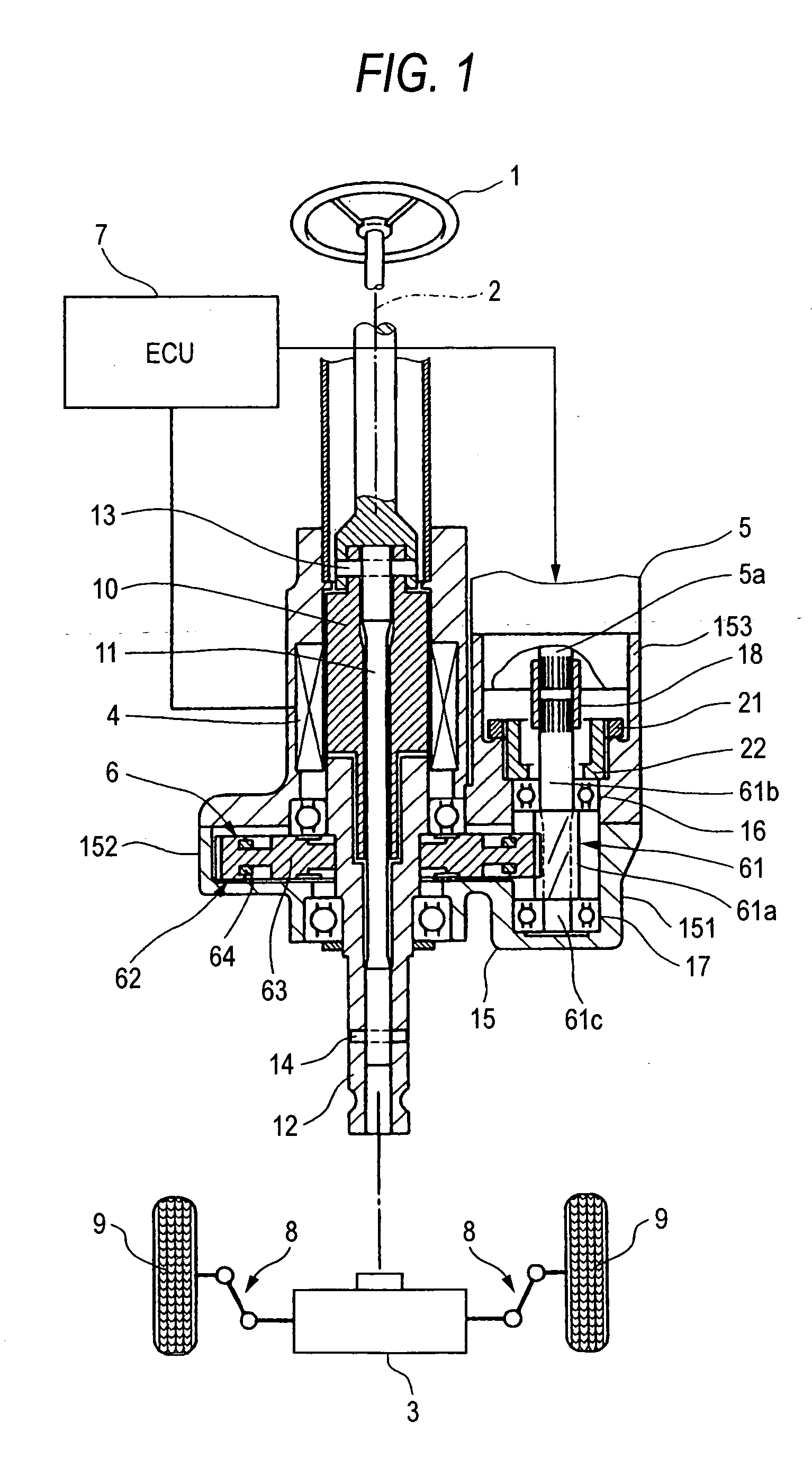
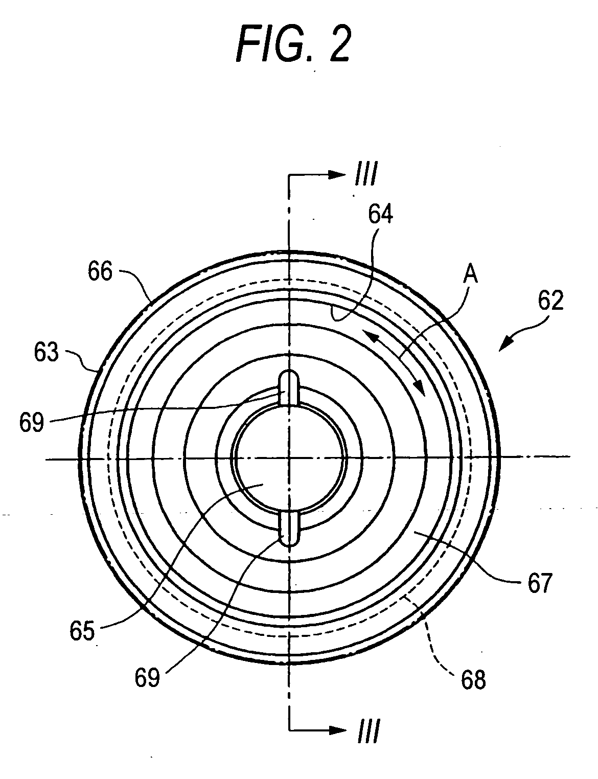
[0031] An electric power steering system according to a first embodiment of the invention will be described in detail by reference to the accompanying drawing. FIG. 1 is a sectional view of a speed reduction mechanism portion of the electric power steering system in which related configurations are also shown. FIG. 2 is a front view of a driven gear, and FIG. 3 is a sectional view taken along the line III-III in FIG. 2.

[0032] The electric power steering system according to the first embodiment includes a steering shaft 2 which is connected to a steering member (a steering wheel) 1 at one end thereof, a steering mechanism 3 made up of a rack-and-pinion mechanism which is connected to the other end of the steering shaft 2, a torque sensor for detecting a steering torque that is applied to the steering shaft 2 through an operation of the steering member 1, an electric motor 5 which generates a steering assist torque for reducing a load borne by a driver when he or she operates the ste...


PUM


Abstract

An electric power steering system which assists in steering by driving an electric motor in accordance with an operation of a steering member, comprising a drive gear connected to a rotation shaft of the electric motor and a driven gear securely fitted on a steering shaft so as to mesh with the drive gear, wherein the driven gear includes a gear body and a ring element that is mounted on the gear body in such a manner as to slide relative to the gear body.

Description

BACKGROUND OF THE INVENTION [0001] The present invention relates to an electric power steering system which assists a driver in steering by driving an electric motor in accordance with an operation by the driver of a steering member such as a steering wheel. [0002] The electric power steering system includes a torque sensor for detecting a steering torque of the steering wheel applied by the driver, the electric motor which assists in steering effort, a speed reduction mechanism which reduces the rotational speed of the electric-motor for transmission to a steering shaft and an electronic control unit (ECU) which controls the electric motor based on sensor signals such as from the torque sensor. [0003] The speed reduction mechanism is made up of a drive gear such as a worm gear connected to a rotation shaft of the electric motor and a driven gear such as a worm wheel securely fitted on the steering shaft and gives a sum of a steering torque that is applied by the operation of the st...

Claims


Application Information

Patent Timeline
Patent Type & Authority Applications(United States)
IPC IPC(8): B62D5/04
CPCB62D5/0412F16F15/124B62D7/224
Inventor KUROUMARU, YOSHIKAZUNAKANO, SHIROU
Owner JTEKT CORP
Learn More