Capillary tube liquid transport device

a liquid transport device and tube technology, applied in the field of capillary structure, can solve the problems of brittle and fragile nature of glass-like materials, difficult packing, shipping, handling, etc., and achieve the effects of stabilizing the liquid chromatography column, minimizing the dead volume of the column, and avoiding limiting its flexibility

Inactive Publication Date: 2006-03-23
WATERS TECH CORP
View PDF22 Cites 12 Cited by
  • Summary
  • Abstract
  • Description
  • Claims
  • Application Information

AI Technical Summary

Benefits of technology

[0017] In an advantageous embodiment of the devices described above, the fourth cylinder is a tube of heat shrinkable material. The inner diameter of the fourth cylinder before shrinking is approximately the same as the outer diameter of the second and third cylinders, which are approximately equal. This allows the fourth cylinder to be easily slipped over the first, second and third cylinder assembly. The inner diameter of the heat shrink fourth cylinder, once shrunken, is approximately one-half the pre-shrunken diameter. In a preferred configuration, the shrunken inner diameter of the fourth cylinder is greater than the outer diameter of the first cylinder, allowing the fourth cylinder to protect the first cylinder without limiting its flexibility. The shrinking action of the fourth cylinder retains the cylinders in the fixed relationship of their assembly, making the whole assembly more immune to shocks and breakage. When the fifth cylinder, or transfer tube, is joined to the assembly of cylinders before the fourth cylinder is threaded over the assembly, the fourth cylinder may extend beyond the second end of the third cylinder. While the in the preferred embodiment, where the first and fifth cylinders have the same outer diameter, the heat shrunk cylinder will not grip the outer surface of the fifth cylinder, it will provide support to the butted junction between the first and fifth cylinders.
[0018] In one embodiment, the invention is implemented as a liquid chromatography column device with a column that is sized and dimensioned for chromatographic use. The column element has an internal cavity with a first and a second end and a longitudinal axis. A first cylindrical element is disposed about the column first end, forming a reinforced first region of the column. A second cylindrical element is disposed about the column second end. A third cylindrical element has a first end concentrically disposed on the first cylindrical element and a second end concentrically disposed on the second cylindrical element. The third cylindrical element is secured to the cylindrical elements that are encircled thereby stabilizing the liquid chromatography column while allowing it to remain flexible. The column device so assembled is ready to be directly coupled to liquid chromatography equipment in a manner that minimizes column dead volume.

Problems solved by technology

The connection mechanisms are an important part of the system, because they present opportunities for mismatch which at these volumes lead to bandspreading in the resultant analysis.
However, fused silica capillaries have certain limitations.
The most significant limitation stems from the brittle and fragile nature of the glass-like material from which they are made.
The frangible nature of a thin, fused silica tube makes packing, shipping, and handling difficult.
However, if the polyimide layer has incurred even a small scratch during production or handling, it will lose its protective effect and the capillary can break with just a gentle touch.
A skilled person is needed to assemble this end without breaking part of the column or introducing dead volume, that leads to bandspreading that negatively impacts the performance.
During this operation, the transfer tube will be exerting stresses on the bonded joint possibly introducing dead volume into the joint.
This junction is very weak and susceptible to breakage or additional bandspreading.
Fused silica capillaries are extremely fragile and difficult to work with.

Method used


Image

  • Capillary tube liquid transport device
  • Capillary tube liquid transport device
  • Capillary tube liquid transport device

Examples


Embodiment Construction

[0033] The present invention will be described in detail as a device for transporting liquids, performing chromatography and linking other instruments including, by way of example, a mass spectrometer to a liquid chromatograph. However, it must be appreciated that these are preferred embodiments and the invention can be applied in other ways as will be appreciated by those who are skilled in the art.

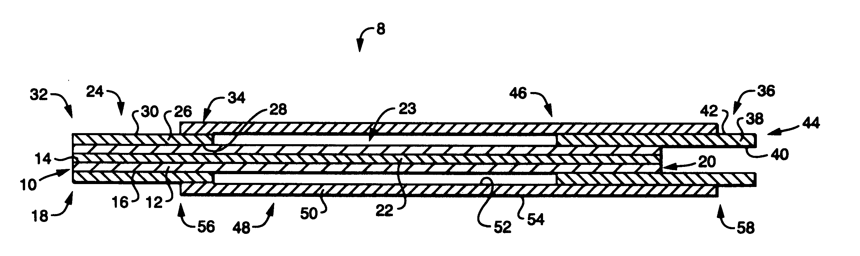
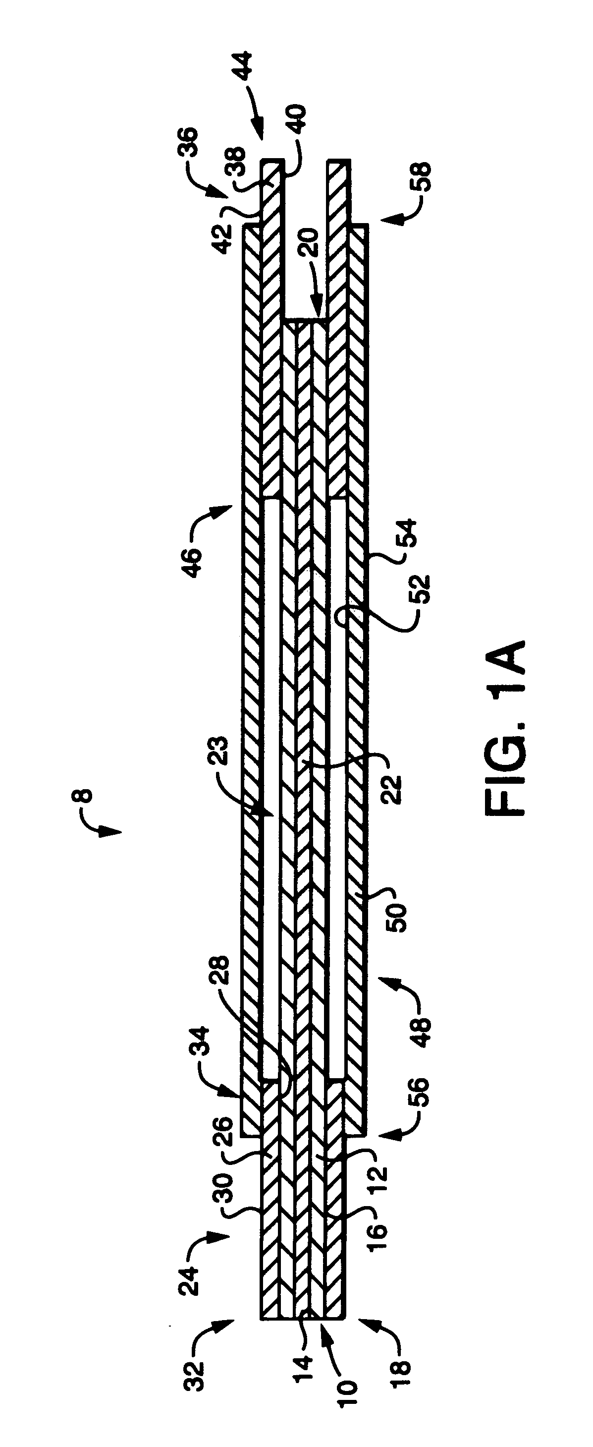
[0034] A preferred embodiment of the invention is used to transport liquids through nano-scale capillary tubes. FIG. 1A illustrates a basic version of this device 8. The device is built around a first cylinder 10 having a wall 12. The wall 12 has an interior surface 14 and an exterior surface 16. This first cylinder has a first end 18, usually connected to an inlet mechanism, and a second end 20, usually connected to an outlet system. The interior volume of the first cylinder 10, surrounded by the interior surface 14, defines a chamber 22 for receiving a liquid sample.

[0035] A second c...


PUM

PropertyMeasurementUnit
diameteraaaaaaaaaa
diameteraaaaaaaaaa
diameteraaaaaaaaaa

Abstract

A capillary tube liquid transport device adapted to make nano-sized capillaries (5 μm to 180 μm) resilient. A first nano-capillary has a first sleeve about an inlet end that provides a resilient surface for installation of a fitting. The nano-capillary has a second sleeve about an outlet end that deforms to grip the outlet end of the capillary and hold it tightly against a transport tubing capillary. An outer sleeve is attached to the two end sleeves retaining them in a spaced relationship and providing support for the capillaries. The entire device is relatively rugged and easy to handle.

Description

CROSS REFERENCE TO RELATED APPLICATIONS [0001] This application claims benefit of and is a continuation of International Application No. PCT / US2004 / 006712, filed Mar. 5, 2004 and designating the United States, which claims benefit of a priority to U.S. Provisional Application No. 60 / 652,742, filed Mar. 7, 2003 (attorney docket number WAA-313). The content of which is expressly incorporated herein by reference in its entirety.FIELD OF THE INVENTION [0002] The invention relates to a capillary structure that may include a column and more particularly to an assembly that stabilizes a capillary for ease of use in a liquid chromatography application. BACKGROUND OF THE INVENTION [0003] Capillary liquid chromatography (LC) is a micro-version of traditional liquid chromatography. Capillary LC columns have extremely low solvent consumption and require ultra-low volumes of samples for analysis, and hence provide high efficiency separations. Nano LC is an even smaller version of Capillary LC, t...

Claims


Application Information

Patent Timeline
Patent Type & Authority Applications(United States)
IPC IPC(8): B01D15/08G01N30/60
CPCG01N30/6034G01N30/6095G01N30/6078G01N30/6047B01D15/08
Inventor BENEVIDES, CHRISTOPHER C.COLLAMATI, ROBERTDELLAROVERE, DENNIS
Owner WATERS TECH CORP
Why Eureka
Try Eureka