
System and method for capturing image sequences at ultra-high framing rates

Inactive Publication Date: 2006-03-23
WICHITA STATE UNIVERSITY
View PDF23 Cites 102 Cited by
  • Summary
  • Abstract
  • Description
  • Claims
  • Application Information

AI Technical Summary

Benefits of technology

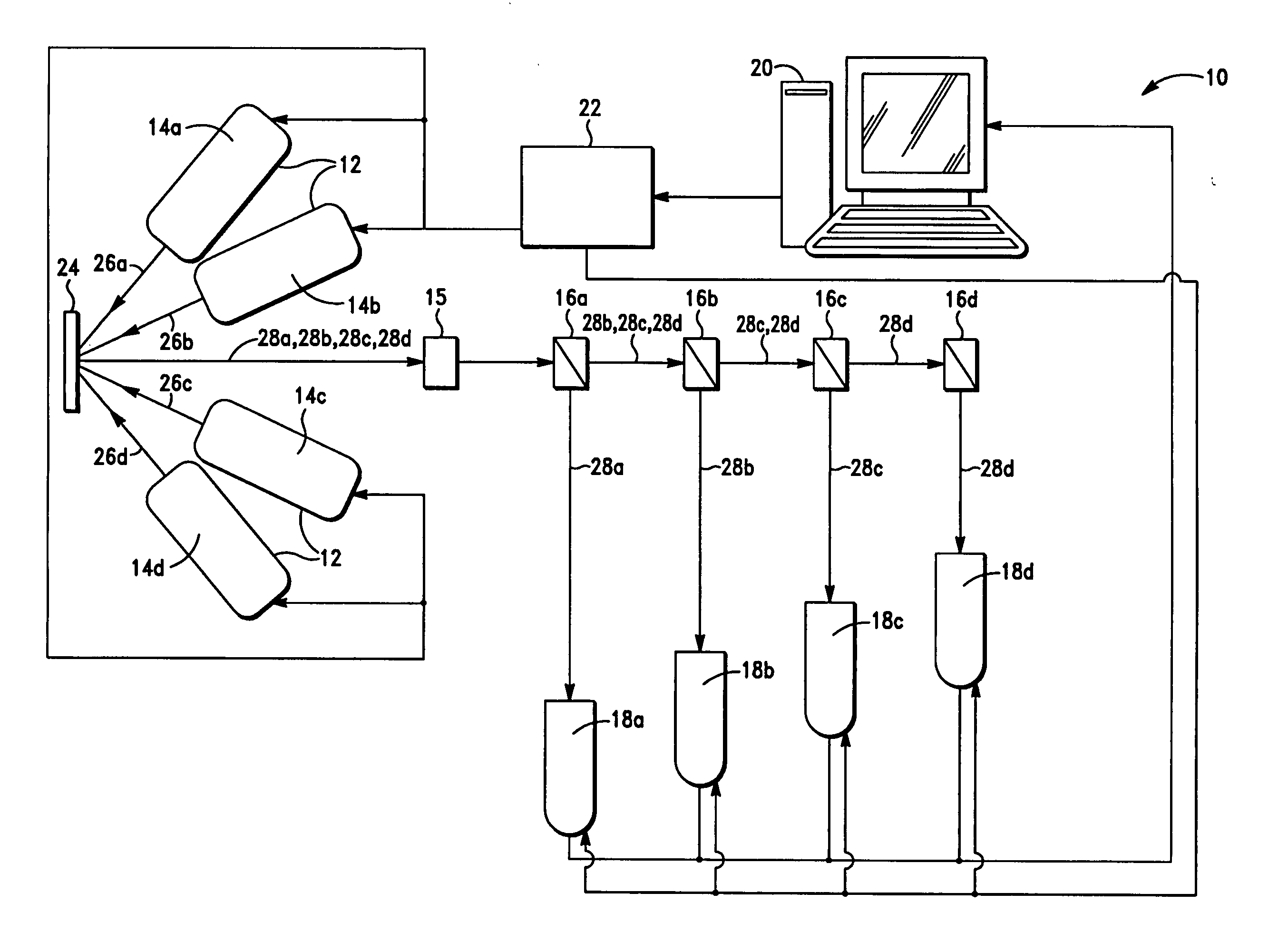
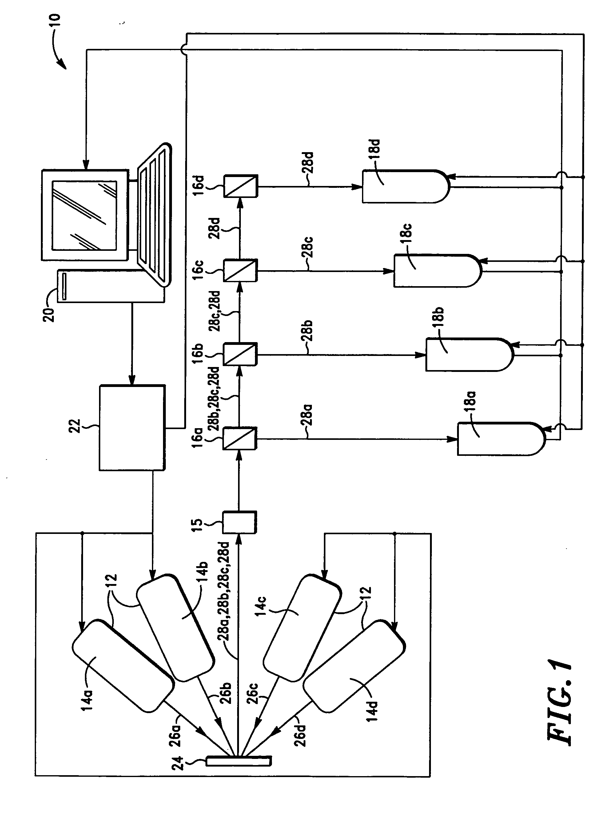
[0019] In a second exemplary embodiment, the system comprises three dual-cavity pulsed lasers and four non-intensified dual-frame cameras mounted on a stereo microscope. Two of the dual-cavity pulsed lasers are used to illuminate the target for visual imaging, and the third dual-cavity pulsed laser is used to excite a phosphor coating on the target for fluorescent imaging. Two of the dual-frame cameras are mounted so as to share a first viewing axis of the stereo microscope, and the other two dual-frame cameras are mounted so as to share a second viewing axis of the stereo microscope. Again, both frames of each of the dual-frame cameras are advantageously used for image capture. In operation, the dual-cavity pulsed lasers and the dual-frame cameras may be triggered in such a manner as to simultaneously capture a series of four visual images (or two stereo images) of the target and two fluorescence images of the target. The visual images may then be processed using digital image correlation software to obtain a deformation field of the target, and the fluorescence images may be processed using two-line laser induced fluorescence software to obtain a temperature field of the target. Therefore, this system allows the simultaneous observation of the deformation and temperature fields of the target at ultra-high framing rates.

Problems solved by technology

The primary limitation on the maximum framing rates that may be achieved is the time required to readout a captured image to the memory device.
Thus, even with the fastest available image sensors, the framing rates of these imaging systems cannot exceed a few kilohertz (kHz) (for high resolution images) due to the limitation on readout time.
While framing rates of up to 1 megahertz (MHz) may be achieved, this technique also decreases the spatial resolution or size of the images.
The problem with the use of image intensifiers, however, is that they degrade the quality of the resulting images.
Thus, this type of imaging system is not well-suited for techniques that require high quality images, such as digital image correlation and particle image velocimetry.
While this type of imaging system does not require the use of image intensifiers, the framing rates are limited to a few megahertz because of the technical limitations imposed by the high-speed rotating mirror (e.g., a rotational speed of 4,000 revolutions per second is needed to capture images at a framing rate of 1 MHz) and the image blurring (known as image drag for this type of camera) caused by the rotation of the mirror.
However, because the time between light pulses must be greater than the time required to transfer a captured image from the image region to the memory region, the framing rates that may be achieved with this type of imaging system cannot exceed 10 MHz (for cameras with the shortest frame transfer time of 100 nanoseconds given that the exposure time can be set to be 100 nanoseconds or less).
Note that if dual-frame cameras were used, the second image is unusable due to the long exposure time during which multiple exposures would occur.

Method used


Image

  • System and method for capturing image sequences at ultra-high framing rates
  • System and method for capturing image sequences at ultra-high framing rates
  • System and method for capturing image sequences at ultra-high framing rates

Examples


example 1

[0052] Referring to FIG. 4, an imaging system 100 in accordance with a first exemplary embodiment of the present invention may be used to capture eight visual images of a target 102. These eight visual images may then be processed using digital image correlation software to obtain a time history of the deformation field of target 102.

[0053] As shown in FIG. 4, imaging system 100 includes four dual-cavity lasers 104a, 104b, 104c, 104d each of which is operable to emit two light pulses in quick succession. In this example, each of lasers 104a, 104b, 104c consists of a dual-cavity, Q-switched Nd:YAG laser that has been frequency-tripled to emit light pulses at a wavelength of 355 nanometers. Laser 104d consists of a dual-cavity, Q-switched Nd:YAG laser that has been frequency-doubled to emit light pulses at a wavelength of 532 nanometers. The light pulses emitted from dual-cavity lasers 104a, 104b, 104c are directed to wavelength shifters 106a, 106b, 106c, respectively, each of which ...

example 2

[0063] Referring to FIG. 5, an imaging system 200 in accordance with a second exemplary embodiment of the present invention may be used to simultaneously capture four visual images and two fluorescence images of a target 202. The four visual images may be processed using digital image correlation software to obtain a deformation field of target 102. The two fluorescence images may be processed using laser induced fluorescence software to obtain a temperature field of target 202.

[0064] As shown in FIG. 5, imaging system 100 includes two dual-cavity lasers 204a, 204b, each of which is operable to emit two light pulses in quick succession. In this example, each of lasers 204a, 204b consists of a dual-cavity, Q-switched Nd:YAG laser that has been frequency-tripled to emit light pulses at a wavelength of 355 nanometers. The light pulses emitted from dual-cavity lasers 204a, 204b are directed to wavelength shifters 206a, 206b, respectively, each of which shifts the wavelength of the ligh...


PUM


Abstract

An imaging system for capturing a sequence of images from a target at ultra-high framing rates is disclosed. The imaging system includes an illumination system operable to emit at least first and second light pulses at first and second wavelengths, respectively. The first and second light pulses sequentially illuminate the target whereupon at least first and second propagated light pulses emanate from the target. The system also includes at least first and second image sensors operable to receive the first and second propagated light pulses, respectively, to thereby capture the sequence of images from the target. Various exemplary embodiments of the imaging system and associated method are provided.

Description

CROSS-REFERENCE TO RELATED APPLICATIONS [0001] Not applicable. STATEMENT REGARDING FEDERALLY SPONSORED RESEARCH OR DEVELOPMENT [0002] Not applicable. BACKGROUND OF THE INVENTION [0003] 1. Field of the Invention [0004] The present invention relates to imaging systems and, in particular, to imaging systems that are capable of capturing a sequence of full resolution images at ultra-high framing rates for use in obtaining deformation and / or temperature field measurements of a target under observation. [0005] 2. Description of Related Art [0006] High speed imaging systems are widely used in a variety of scientific fields to observe high speed events. Most imaging systems include a light source that illuminates a target, and an image sensor (e.g., a charge coupled device (CCD) array) that captures an image from the target for readout to a memory device. The primary limitation on the maximum framing rates that may be achieved is the time required to readout a captured image to the memory d...

Claims


Application Information

Patent Timeline
IPC IPC(8): H04N5/222
CPCH04N5/2251H04N13/0253H04N13/0242H04N5/232H04N13/243H04N13/254H04N23/60
Inventor MADHAVAN, VISWANATHANHIJAZI, ALA
Owner WICHITA STATE UNIVERSITY
Learn More