Optical pickup spherical aberration compensating method, optical pickup sherical aberration focus offset compensating method, and optical pickup device

Inactive Publication Date: 2006-03-23
SHARP KK
View PDF1 Cites 19 Cited by
  • Summary
  • Abstract
  • Description
  • Claims
  • Application Information

AI Technical Summary

Benefits of technology

[0050] Thus, the spherical aberration and focus offset of a writeable optical disc can be corrected quickly and accurately.
[0051] The method of correcting a spherical aberration focus offset of an optical pickup of the present invention is characterized in that a spherical aberration and/or a focus offset are produced which maximize an amplitude of the reproduced signal.
[0052] According to the arrangement, since a reproduction signal of the recorded information of which the quality must be ensured by the optical pickup is directly designated as a reference signal, the resultant correction is accurate, needs no complex signal processing, and is implemented on a simple circuit.
[0053] The method of correcting a spherical ab

Problems solved by technology

However, it is difficult in manufacturing to fabricate the transparent substrates in all optical discs with the same specified thickness; irregularities of a few or 10 to 40 micrometers are typical.
The irregular thickness of the transparent substrate results in spherical aberration which in turn can markedly reduce the amplitude of an information readout signal and/or tracking error signal.
This entails inaccurate information readout.
Specifically, when changing optical discs, there will likely be a difference in thickness between the transparent substrates.
The difference translates into a change in spherical aberration and without taking any measures, causes a fall in information readout accuracy.
Tokukai 2000-11388, a conventional art, has a problem that it is not applicable to discs without prepit signals.
In addition, the prepit signal is stored, for example, in sector marks which in general give such a small amount of data that the areas may not be sufficient to enable accurate observation of the magnitude of the correction of the spherical aberration.
Moreover, in cases of write once, rewriteable, and

Method used


Image

  • Optical pickup spherical aberration compensating method, optical pickup sherical aberration focus offset compensating method, and optical pickup device
  • Optical pickup spherical aberration compensating method, optical pickup sherical aberration focus offset compensating method, and optical pickup device
  • Optical pickup spherical aberration compensating method, optical pickup sherical aberration focus offset compensating method, and optical pickup device

Examples


embodiment 1

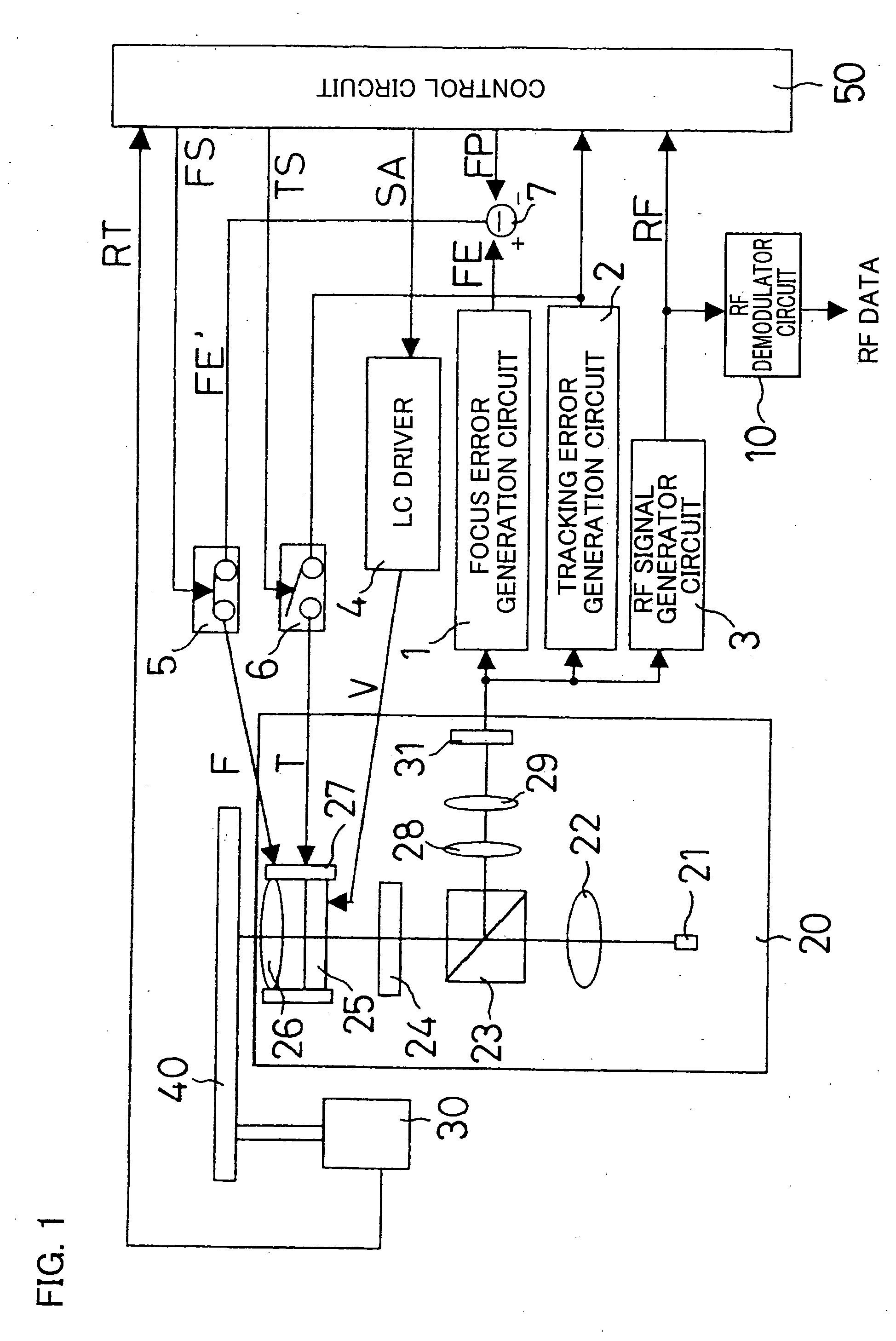
[0084]FIG. 1 depicts the construction of an optical pickup which is the first embodiment of the present invention. In FIG. 1, a pickup 20 emits a read beam onto an optical disc 40 as an optical storage medium which rotates as driven by a spindle motor 30, and receives a reflection from the disc 40. In the driving, for every revolution of the optical disc 40, the spindle motor 30 generates a revolution signal RT for output to a control circuit 50. After shining a read beam onto the optical disc 40 and receiving its reflection, the pickup 20 converts that incoming light to an electric signal for output to a focus error generation circuit 1, a tracking error generation circuit 2, and a RF signal generator circuit 3.

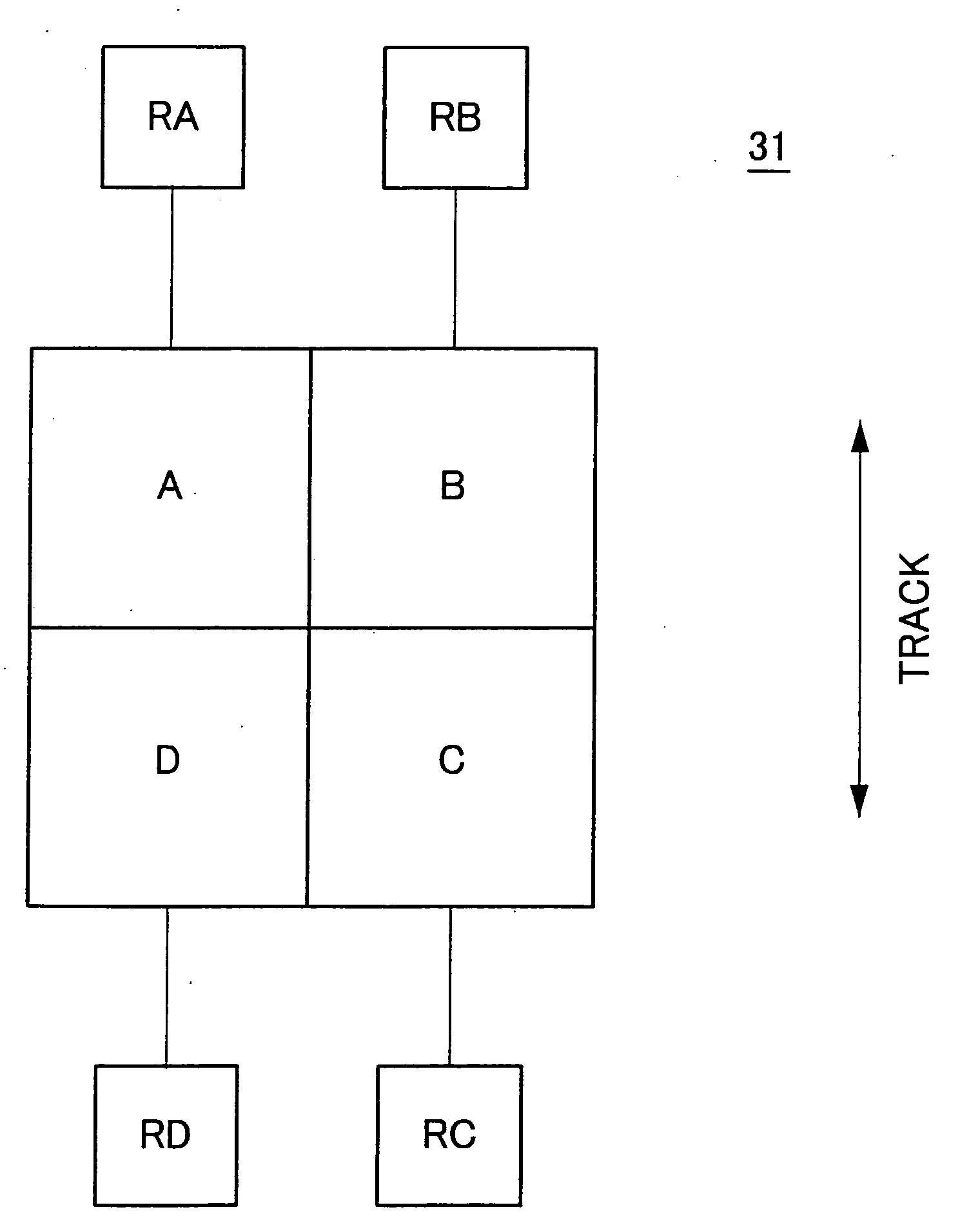
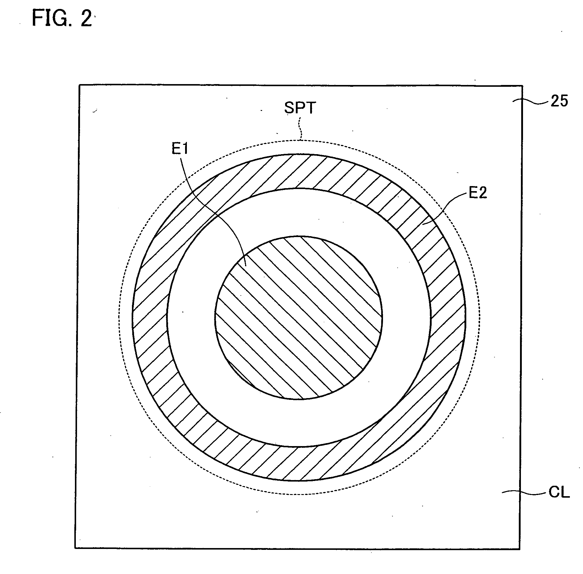
[0085] The pickup 20 contains a laser producing element 21, a collimating lens 22, a beam splitter 23, a quarter-wave plate 24, a liquid crystal panel 25, an objective lens 26, a focusing tracking actuator 27, a collective lens 28, a cylindrical lens 29, and an optical sens...

embodiment 2

[0111] The following will describe the second embodiment of the present invention in detail with reference to figures. FIG. 6 illustrates the construction of an optical pickup which is the second embodiment of the present invention. In FIG. 6, a pickup 20 emits a read beam onto an optical disc 40 as an optical storage medium which rotates as driven by a spindle motor 30, and receives a reflection from the disc 40. In the driving, for every revolution of the optical disc 40, the spindle motor 30 generates a revolution signal RT for output to a control circuit 50. After shining a read beam onto the optical disc 40 and receiving its reflection, the pickup 20 converts that incoming light to an electric signal for output to a focus error generation circuit 1, a tracking error generation circuit 2, and a RF signal generator circuit 3.

[0112] The pickup 20 contains a laser producing element 21, a collimating lens 22, a beam splitter 23, a quarter-wave plate 24, a beam expander 35, a beam e...

embodiment 3

[0147] Next, a third embodiment of the present invention will be described in detail in reference to figures.

[0148]FIG. 12 shows the RF level changing with changes of the lens distance of a beam expander 35 in spherical aberration correction. The beam expander 35 here is in an optical pickup of the present embodiment which is arranged similarly to the FIG. 6 embodiment. The optical pickup has a spherical aberration left uncorrected (first spherical aberration). In FIG. 12, similarly to FIG. 7, the spherical aberration of the device is plotted on the horizontal axis, and the RF level of an information signal is plotted on the vertical axis. The RF level is a maximum at zero spherical aberration. The RF level hardly changes at aberrations equal to or less than a reference value for optical characteristics evaluation. Well-known reference values for evaluation are, as mentioned earlier, the Rayleigh limit (defining a maximum value of wavefront aberration at λ / 4 or less) and SD (Strehl...


PUM


Abstract

An optical pickup (20) projects a read beam onto an optical disc (40) as an optical storage medium which is driven to rotate by a spindle motor (30) and receives its reflection. A laser beam from a laser producing element (21) passes through a liquid crystal panel (25) and guided to an objective lens (26). The panel (25) is provided to correct spherical aberration caused by an irregular thickness of a transparent substrate of the optical disc (40). A control circuit (50) changes a spherical aberration correction signal SA to carry out sampling more than once, covering a range of the output of an optical sensor (31) where the output shows large changes. The circuit (50) determines the position of a peak of an approximation curve through calculation and designates that position as the magnitude of correction. Thus, the optical pickup (20) can quickly and accurately detect the magnitude of the correction of the spherical aberration caused by an irregular thickness of the optical disc (40).

Description

TECHNICAL FIELD [0001] The present invention relates to a spherical aberration correction method for optical pickups which are used in reading / writing compact discs (CD), laser discs (LD), digital versatile discs (DVD), and other like optical storage media, and relates also to a spherical aberration focus offset correction method for those optical pickups and the optical pickups. BACKGROUND ART [0002] Read / write optical pickups have been used in optical readers for read-only CDs, LDs, DVDs and other similar optical discs and also in optical reader / writer for write once or rewriteable optical discs, such as CD-Rs, CD-RWs, DVD-Rs, DVD-RWs, DVD-RAMs, and mini discs (MDs). [0003] Optical discs as optical storage media have a transparent substrate with a predetermined thickness to cover their recording surface for protective purposes. An optical pickup as information readout means reads the optical disc by the intensity of reflection when a read beam is shone on the recording surface thr...

Claims


Application Information

Patent Timeline
IPC IPC(8): G11B7/00G11B7/09G11B7/135
CPCG11B7/13927G11B7/0945
Inventor MIYAKE, TAKAHIROHORIYAMA, MAKOTO
Owner SHARP KK
Why Eureka
Try Eureka