Microfluidic microarray systems and methods thereof

Active Publication Date: 2006-03-23
SANDIA NAT LAB
View PDF67 Cites 95 Cited by
  • Summary
  • Abstract
  • Description
  • Claims
  • Application Information

AI Technical Summary

Benefits of technology

[0005] In overcoming the problems associated with providing a high throughput microfluidic chip capable of specifically capturing and concentrating nucleic acids for microarray analysis, the present invention provides, inter alia, systems including a manifold comprising a plurality of via holes in fluid communication with a

Problems solved by technology

One drawback of microarray technology in its current format is the long and tedious processing times involved, often requiring up to four d

Method used


Image

  • Microfluidic microarray systems and methods thereof
  • Microfluidic microarray systems and methods thereof
  • Microfluidic microarray systems and methods thereof

Examples


examples

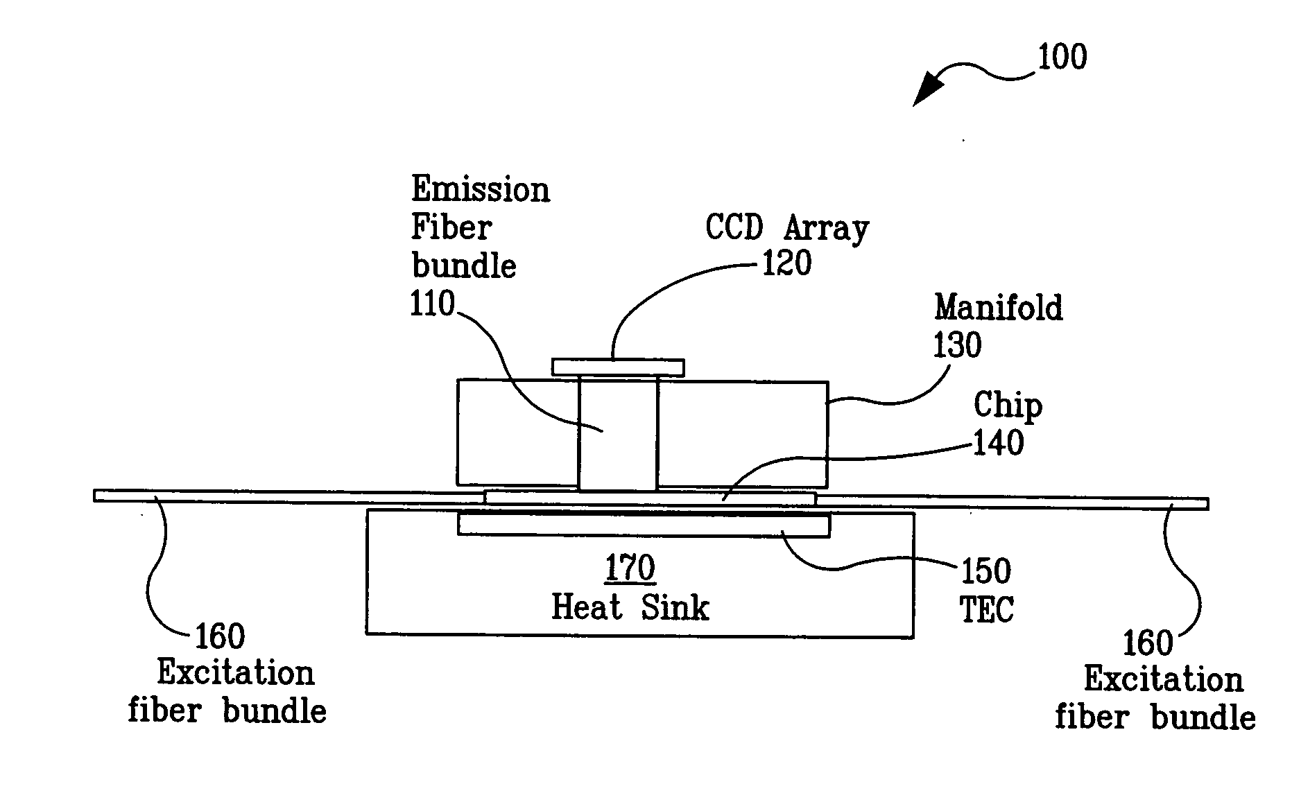
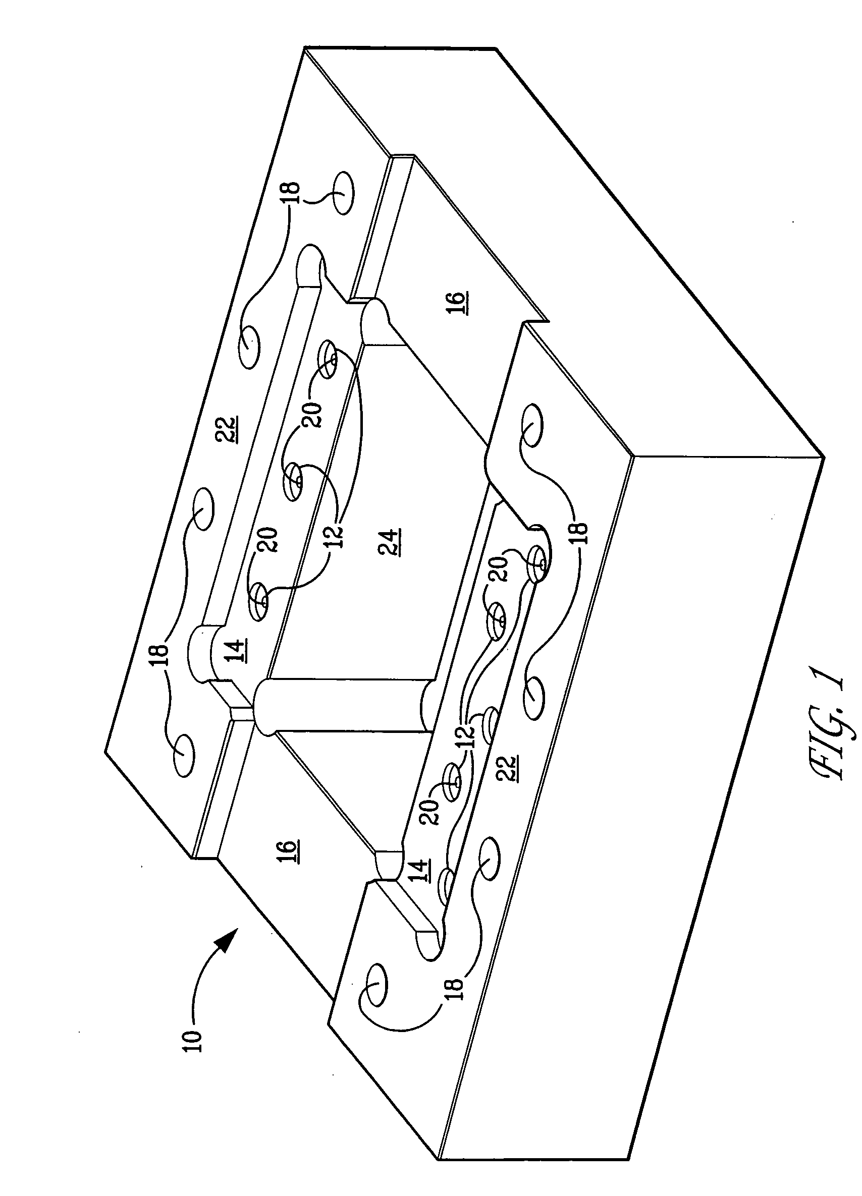
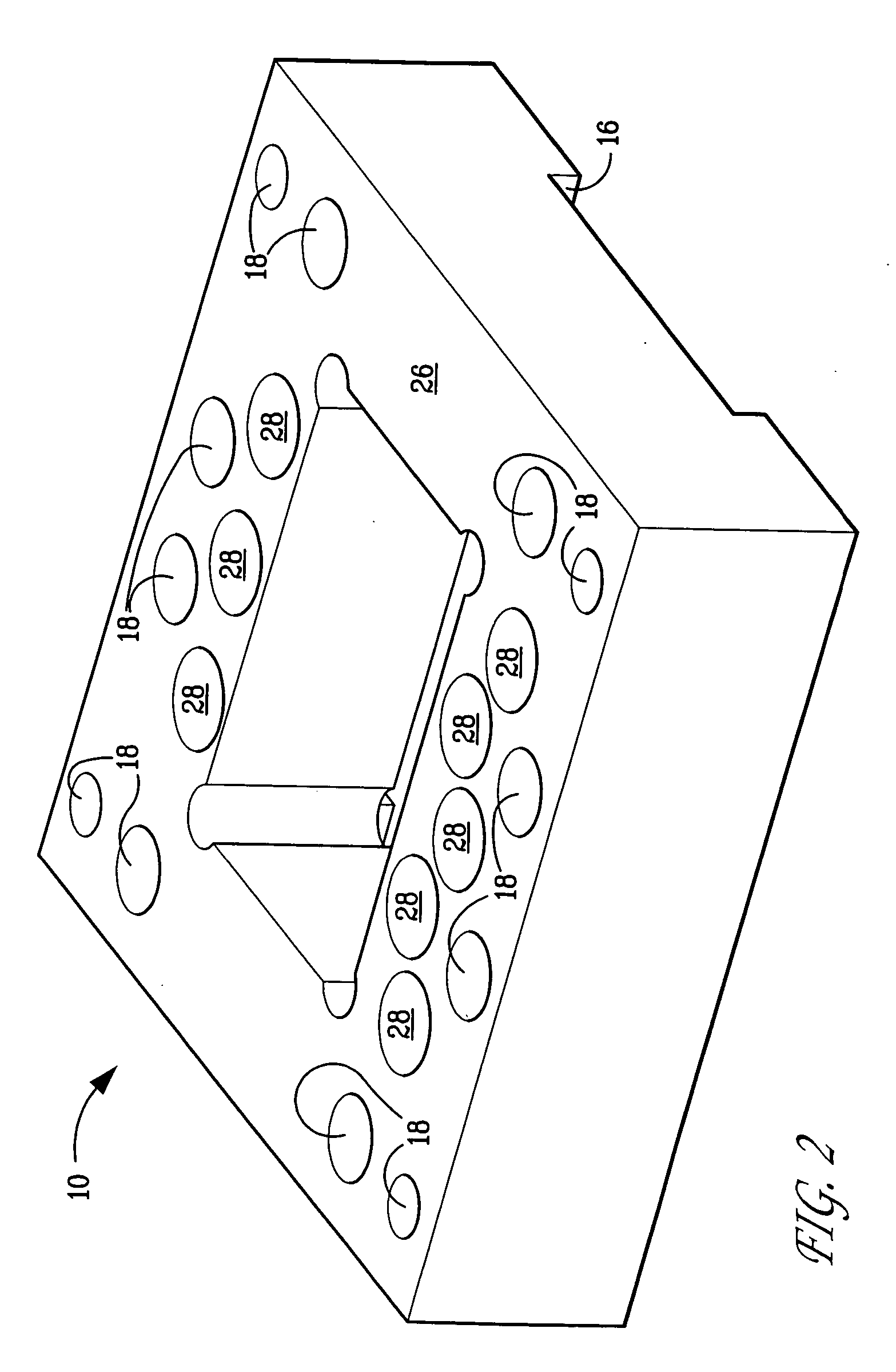
[0049] A system as described herein and illustrated in FIGS. 1-10 was fabricated to establish fluidic connection between microfluidic microarray chips and fluidic reservoirs that contain solutions used for microarray experiments. The system enables detection of microarray probes deposited on the microarray surface in parallel and in real-time. Sample preparation, microarray hybridization and probe / target detection are integrated with illumination of the microarray. The system provides a compact platform for detection applications, including portable sensing of bio-molecules (gene sequences, and proteins) from viruses, bacteria, plants, algae as well as eukaryotes (mammalian cells) or any experiment that could be accomplished on a microarray platform.

[0050] Microarray Preparation and Detection. Detection of a typical microarray is performed after the microarray is spotted and has been hybridized for approximately 12 hours. After this incubation period, the microarray is washed using...


PUM

PropertyMeasurementUnit
Temperatureaaaaaaaaaa
Lengthaaaaaaaaaa

Abstract

Disclosed are systems that include a manifold in fluid communication with a microfluidic chip having a microarray, an illuminator, and a detector in optical communication with the microarray. Methods for using these systems for biological detection are also disclosed.

Description

STATEMENT OF GOVERNMENT INTEREST [0001] This invention is made with Government support under contract no. DE-AC04-94AL85000 awarded by the U.S. Department of Energy to Sandia Corporation. The Government has certain rights in the invention.FIELD OF THE INVENTION [0002] The present invention is related to the field of microfluidic systems and their operation. The present invention is also related to the field of microarrays. BACKGROUND OF THE INVENTION [0003] Recent advances in miniaturization have led to the development of microfluidic systems that are designed, in part, to perform a multitude of chemical and physical processes on a micro-scale. Typical applications include analytical and medical instrumentation, industrial process control equipment, liquid and gas phase chromatography, and the detection of biological weapons. In this context, there is a need for devices that have fast response times to provide precise control over small flows as well as small volumes of fluid (liqui...

Claims


Application Information

Patent Timeline
IPC IPC(8): C12Q1/68C12M1/34
CPCB01L2300/18B01L2300/0877B01L2400/0487C12Q1/6837G01N21/0303B01L2300/1894B01L2300/0654B01J2219/00387B01J2219/00527B01J2219/00576B01J2219/00659B01J2219/00722B01L3/0293B01L3/502715B01L3/565B01L7/52B01L9/527B01L2200/027B01L2200/10B01L2300/0636C12Q2565/629
Inventor WEST, JAY A.A.HUKARI, KYLE W.HUX, GARY A.
Owner SANDIA NAT LAB
Why Eureka
Try Eureka