

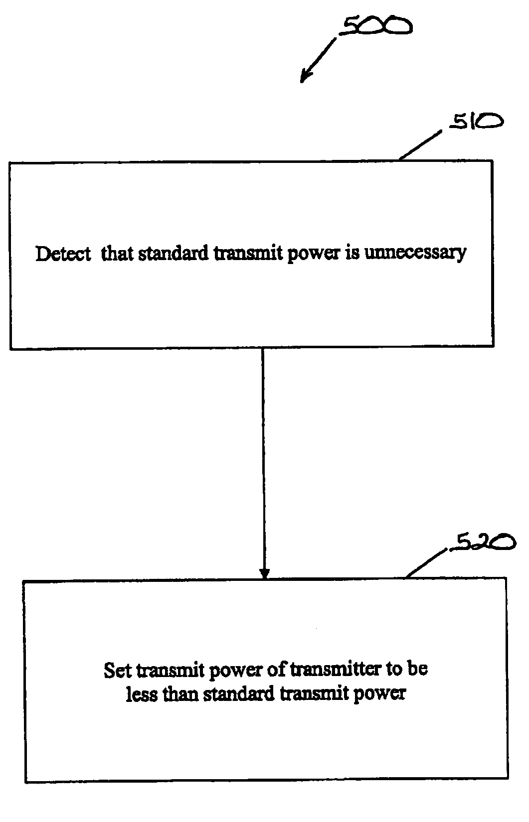
Apparatus and method for transmitting a signal at less than a standard transmit power in a network
a technology of transmitting power and network, applied in the field of network, can solve the problems the power consumed by the transmitter, and achieve the effects of reducing the output power of the transmitter, reducing the current, and reducing the center tap voltage of the transmitter
- Summary
- Abstract
- Description
- Claims
- Application Information
AI Technical Summary
Benefits of technology
Problems solved by technology
Method used
Image

Examples
first embodiment
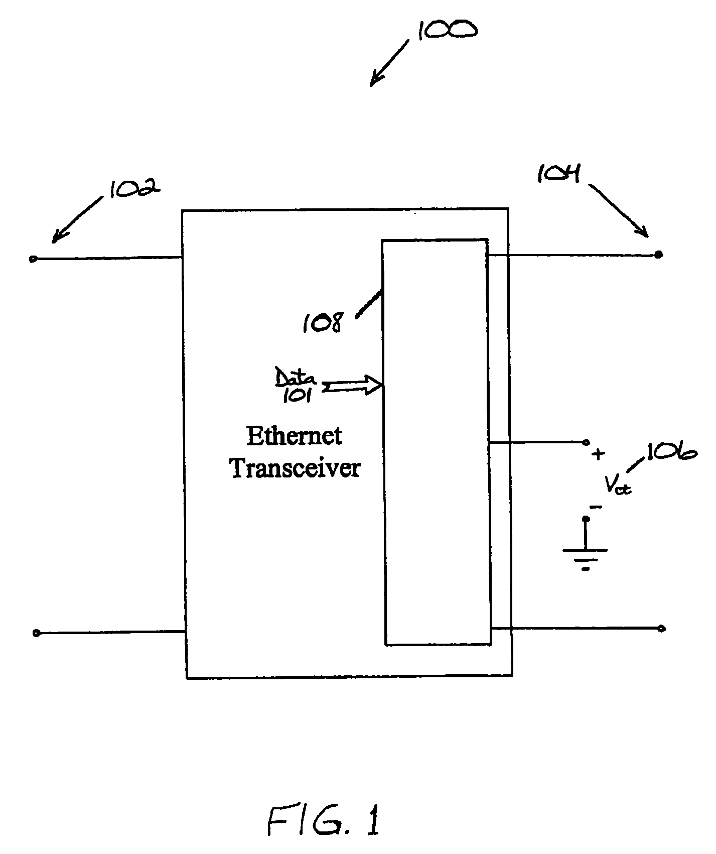
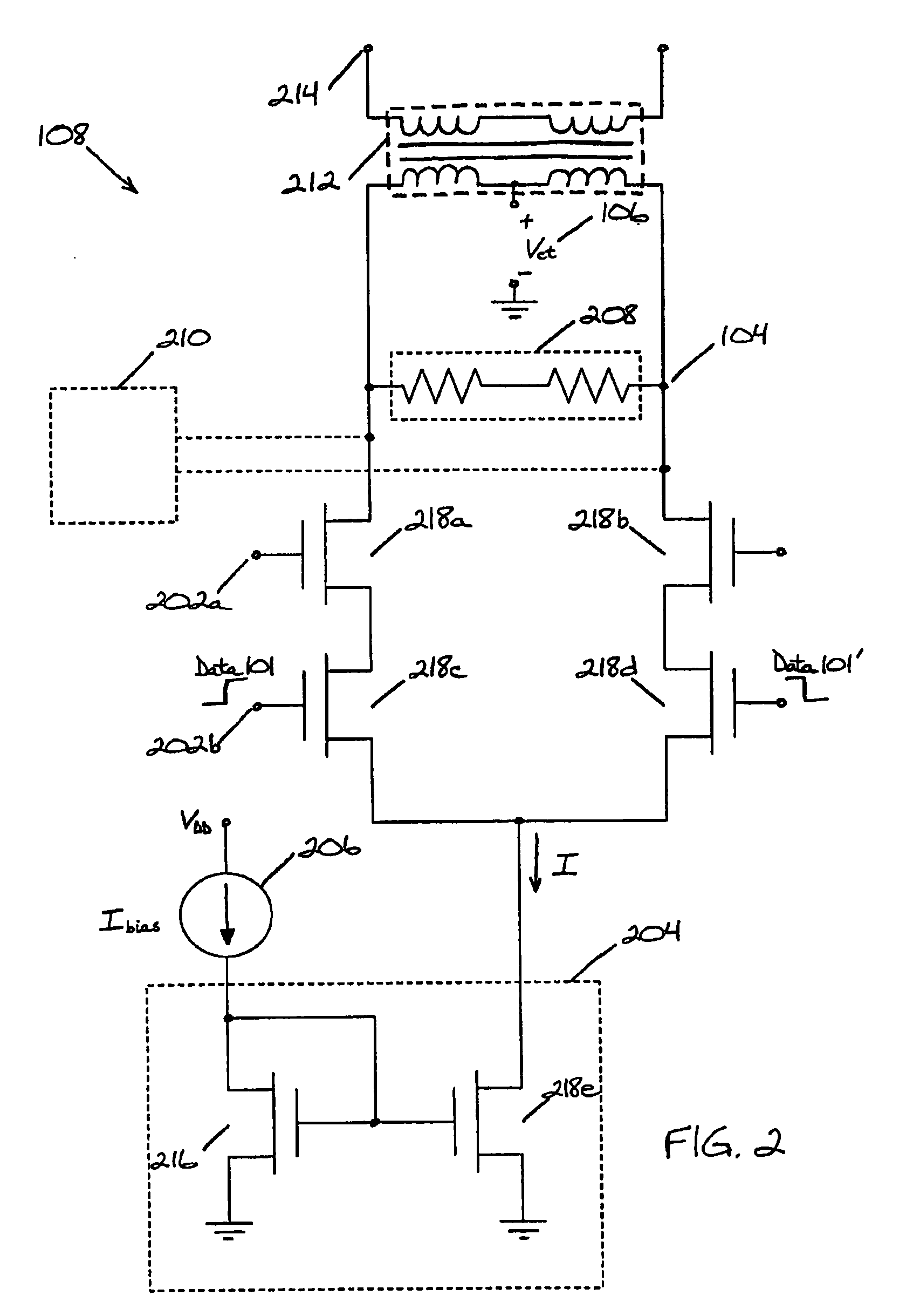
[0045] the power consumption of transmitter 108 is reduced by reducing center tap voltage 106 of transmitter 108. The output voltage (i.e., transmit voltage) of transmitter 108 is based on the launch voltage of transmitter 108. Center tap voltage 106 is set to accommodate the output voltage swing of transmitter 108. The power of transmitter 108 is based on the current I and center tap voltage 106. Thus, reducing the output voltage swing at terminals 104 of transmitter 108 may allow center tap voltage 106 to be reduced, thereby reducing the output power of transmitter 108. Reducing center tap voltage 106 from 2.5 V to 1.8 V, peak-to-peak, may reduce the power consumption of transmitter 108 by approximately 28%, for example. In FIG. 3, center tap voltage 106 is shown to be 0 V for illustrative purposes. Center tap voltage 106 may be set to any value.
[0046] In a second embodiment, the power consumption of transmitter 108 is reduced by changing the class of operation (e.g., Class A, B,...
third embodiment
[0047] the power consumption of transmitter 108 is reduced by connecting diode-connected transistors in parallel in current mirror 204. Current mirror 204 operates by providing a bias current Ibias in a ratio of M:1 to differential output terminals 104, where M is the number of diode-connected transistors coupled in parallel in transmitter 108. Thus, the current I flowing through transistor 218e may be represented by the equation I=Ibias / M.
[0048] Second inputs 202b gate the current I=Ibias / M across resistor 208. The output voltage of transmitter 108 is developed across resistor 208 and provided to communication link 214 via center tapped transformer 212. The output voltage is increased or decreased by adjusting the current mirror ratio of M:1 that feeds resistor 208. In this embodiment, adding or subtracting diode-connected transistor(s) 216 in the reference side of current mirror 204 adjusts the current I that flows through resistor 208.
[0049] In FIG. 3, transmitter 108 includes ...
PUM
 Abstract
Description
Claims
Application Information