System and method for joining superconductivity tape

a superconductivity tape and superconducting technology, applied in the field of superconductor materials, can solve the problems of loss, power dissipation, electric resistance, etc., and achieve the effects of reducing the superconducting properties of the wire, reducing the resistance of the wire, and ensuring the connection

Inactive Publication Date: 2006-03-23
METAL OXIDE TECH
View PDF18 Cites 17 Cited by
  • Summary
  • Abstract
  • Description
  • Claims
  • Application Information

AI Technical Summary

Benefits of technology

[0011] The present invention is directed to a system and method which allows for the splicing of coated conductor superconducting wire or tales. The coated conductor wire is typically comprised of a metal foil substrate which gives the strength and ductility to the wire, a buffer layer or layers which separate the superconducting layer from the substrate and prevent interdiffusion of species that could reduce the superconducting properties of the wire, and the superconducting layer deposited on top of the buffer layer(s). Splicing or joining of such a wire geometry may include structural joining of the metal foil substrate, fill-in of the metal foil substrates over the joint region, fill-in of the buffer layer(s) onto the splice region, and / or overlay of the superconducting layer over the joint with electrical / superconducting connectivity to both sides of the splice. In addition, the atomic order of the substrate, buffer layer(s) and the superconducting layer should be maintained throughout the splice region to make an effective superconducting joint. The present invention uses a portable joiner for joining two superconductor pieces. The joiner includes a support for holding the two superconductor pieces adjacent to each other. The substrate of the first piece is then welded to the substrate of the second piece. A patch made of substrate material may be provided at the weld point of the two pieces to provide more support for the mechanical connection. The patch would be welded to the substrate of both pieces.

Problems solved by technology

Electrical resistance, in some applications, is very undesirable.
For example, in electrical power transmission, electrical resistance causes power dissipation, i.e. loss.
Thus, wires carrying large currents dissipate large amounts of energy.
Moreover, the longer the wire used in either larger transformers, bigger motors or larger transmission distances, the more dissipation, since the resistance in a wire is proportional to its length.
Thus, as wire lengths increase more energy is lost in the wires, even with a relatively small currents.
Consequently, electric power plants produce more energy than that which is used by consumers, since a portion of the energy is lost due to wire resistance.
Thus, there is insufficient thermal energy to scatter the pairs, as reversing the direction of travel of one electron in the pair requires the destruction of the pair and many other pairs due to the complex interdependence.
Consequently, the pairs carry current unimpeded.
A problem with YBCO superconductors specifically, and the oxide superconductors in general, is that they are hard to manufacture because of their oxide properties, and are challenging to produce in superconducting form because of their complex atomic structures.
The smallest defect in the structure, e.g. a disordering of atomic structure or a change in chemical composition, can ruin or significantly degrade their superconducting properties.
Defects may arise from many sources, e.g. impurities, wrong material concentration, wrong material phase, wrong processing temperature, poor atomic structure, and improper delivery of materials to the substrate, among others.
The second way has a practical limitation of about 5 feet.
Heating on one side of the chamber, with a cool down on the other side of the chamber may also induce thermal cracks into the YBCO layer and other layers formed on the metal substrate.
The smaller pieces of tape produced by the second method may be spliced together to form a long length tape, but while the pieces may be superconducting, splice technology is not yet at the point of yielding high quality high temperature superconductor splices.
Consequently, current arrangements for forming superconductors cannot form a long, continuous tape of superconductor material.

Method used


Image

  • System and method for joining superconductivity tape
  • System and method for joining superconductivity tape
  • System and method for joining superconductivity tape

Examples


Embodiment Construction

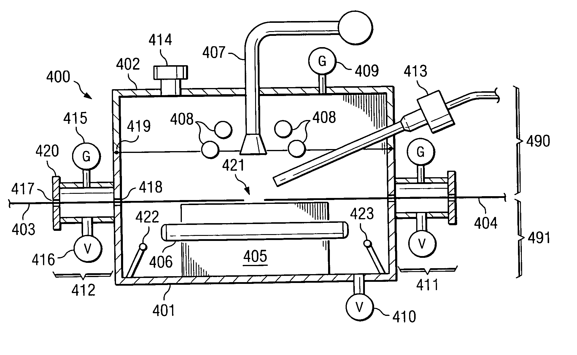
[0023] Various embodiments of the invention are manifested in a portable joiner. The portable joiner is used to join two pieces of superconductor (SC) material and form a single piece of material that retains the superconductive properties of the two pieces. The joiner joins the two pieces both mechanically and electrically. For example, two pieces of SC tape, each of which may be very long in length (e.g. 1000 meters) may be connected by the joiner. Since the joiner is portable, the two pieces that are to be joined may be in the field, and away from the production facility.

[0024]FIG. 4 depicts portable joiner 400 according to various embodiments of the invention. The joiner 400 that connects two superconductor pieces, 403, 404 to form a longer piece of high temperature superconducting (HTS) material. Joiner 400 operates to deposit a layer of SC material that connects the superconductor layers of the two pieces, such that the HTS material is atomically ordered with large, well-orie...


PUM


Abstract

According to an embodiment, a portable system for joining two superconductor pieces comprises a support arranged for holding the two superconductor pieces adjacent to each other in a reaction area, a distribution head positioned to deposit at least one material onto the reaction area used in joining the two superconductor pieces, an ion gun positioned to bombard the reaction area with ions, a gas port arranged for providing at least one gas to the system, and a vacuum port arranged for establishing a desired atmospheric pressure in the system.

Description

CROSS-REFERENCE TO RELATED APPLICATIONS [0001] This application claims priority to U.S. Provisional Patent Application No. 60 / 538,850, filed Jan. 23, 2004 and Unites States Provisional Patent Application No. 60 / 539,310, filed Jan. 26, 2004, the disclosures of which are hereby incorporated herein by reference. This application is related to co-pending and commonly assigned U.S. patent application Ser. No. 10 / 206,123, entitled “METHOD AND APPARATUS FOR FORMING SUPERCONDUCTOR MATERIAL ON A TAPE SUBSTRATE,” filed Jul. 26, 2002, to co-pending and commonly-assigned U.S. patent application Ser. No. 10 / 206,900, entitled “SUPERCONDUCTOR MATERIAL ON A TAPE SUBSTRATE,” filed Jul. 26, 2002, and concurrently filed and commonly assigned U.S. patent application Ser. No. 10 / 206,783, entitled “METHOD AND APPARATUS FOR FORMING A THIN FILM ON A TAPE SUBSTRATE,” filed Jul. 26, 2002, to U.S. patent application Ser. No. ______ [attorney docket no. 5837-P001CP1-10311280] filed concurrently herewith and en...

Claims


Application Information

Patent Timeline
Patent Type & Authority Applications(United States)
IPC IPC(8): H01L39/22H01L39/02H01L39/24H01R4/68
CPCH01L39/02H01R4/68H01L39/24H10N60/80H10N60/0464
Inventor IGNATIEV, ALEXMOLODYK, ALEXANDER A.CASTELLANI, LOUIS D.
Owner METAL OXIDE TECH
Why Eureka
Try Eureka